background image

9

3684A050 Installation Instructions

Bolt Torque

Checking Bolt Torque

The tables shown give correct torque values for various 
bolts and capscrews. Tighten all bolts to the torque 
values specified in the table, unless indicated otherwise. 
Check tightness of bolts periodically. 

IMPORTANT! If replacing hardware, use fasteners of the 
same grade.

IMPORTANT! Torque figures indicated in the table are 
for non-greased or non-oiled threads. Do not grease or 
oil threads unless indicated otherwise. When using a 
thread locker, increase torque values by 5%.

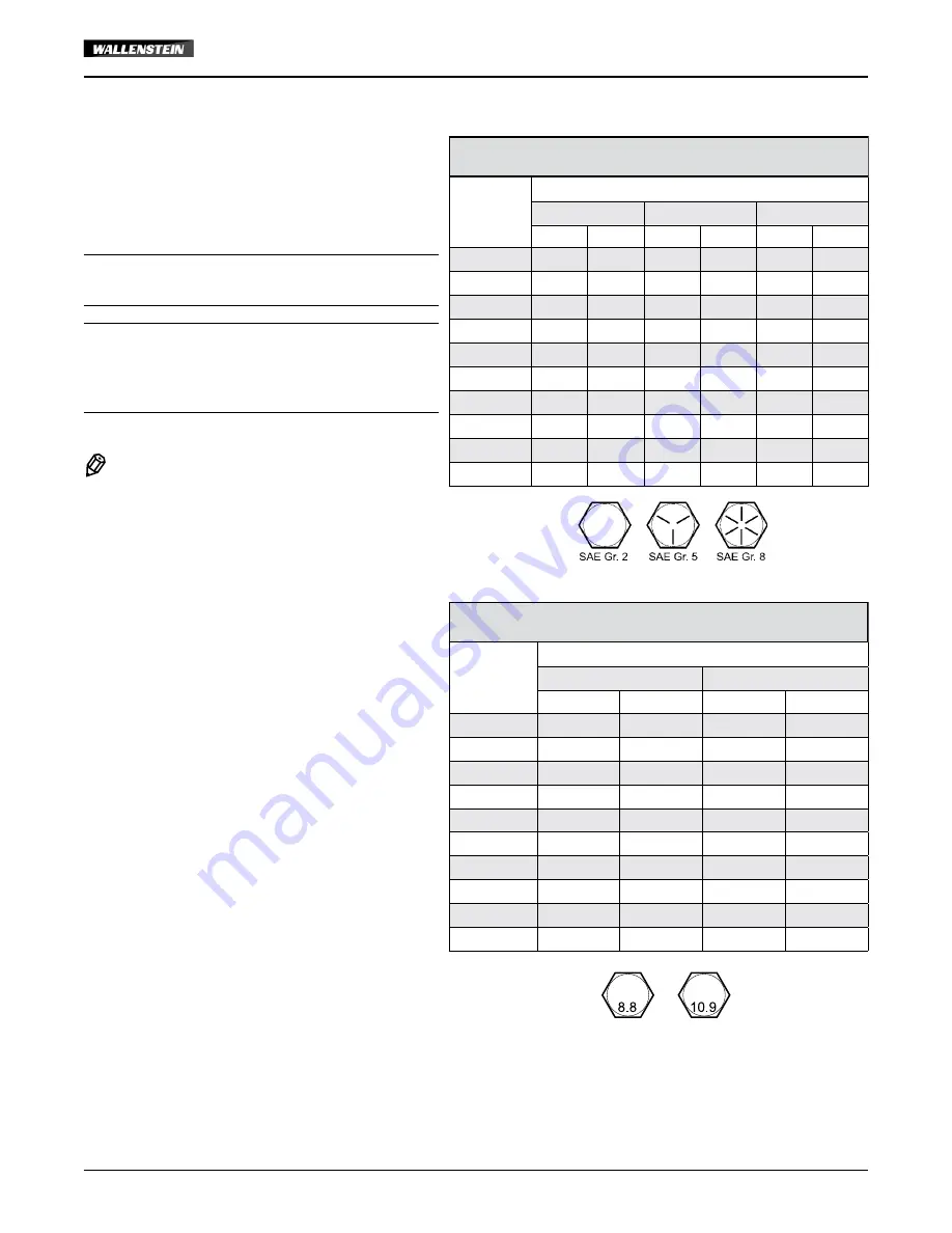
 NOTE:

Bolt grades are identified by their 

head markings.

Imperial Bolt Torque Specifi cations

Bolt 

Diameter

Torque Value

SAE Gr. 2

SAE Gr. 5

SAE Gr. 8

lbf•ft

N•m

lbf•ft

N•m

lbf•ft

N•m

1/4"

6

8

9

12

12

17

5/16"

10

13

19

25

27

36

3/8"

20

27

33

45

45

63

7/16"

30

41

53

72

75

100

1/2"

45

61

80

110

115

155

9/16"

60

95

115

155

165

220

5/8"

95

128

160

215

220

305

3/4"

165

225

290

390

400

540

7/8"

170

230

420

570

650

880

1"

225

345

630

850

970

1320

Metric Bolt Torque Specifi cations

Bolt 

Diameter

Torque Value

Gr. 8.8

Gr. 10.9

lbf•ft

N•m

lbf•ft

N•m

M3

0.4

0.5

1.3

1.8

M4

2.2

3

3.3

4.5

M6

7

10

11

15

M8

18

25

26

35

M10

37

50

52

70

M12

66

90

92

125

M14

83

112

116

158

M16

166

225

229

310

M20

321

435

450

610

M30

1,103

1 495

1,550

2 100

Summary of Contents for 3684A050

Page 1: ...3684A050 INSTALLATION INSTRUCTIONS Backhoe Sub frame Kit Front 3684A050 Rev Nov 2021 ...

Page 2: ...stein Backhoe requires that you and anyone else who will be operating or maintaining the machine read and understand the Safety Operation Maintenance and Trouble Shooting information contained within the Operator s Manual IMPORTANT This installation kit includes both metric and Imperial fasteners Bolt type is identified by looking at the bolt head markings Metric Imperial Operator Orientation The ...

Page 3: ...ame backhoe and tractor are positioned on dry level ground The area around them should be clear and free of debris Make sure the tractor is shut off the brake is applied and key is removed WARNING Review and understand the operating instructions for the backhoe Part of the installation process includes operating the hydraulics to position the attachment points on the tractor WARNING Proceed with c...

Page 4: ... RH 1 10 Z12120 Lynch Pin 1 4 2 Item No Part No Description Qty 11 Z71515 Hex Bolt 1 2NC x 1 1 2 6 12 Z71520 Hex Bolt 1 2NC x 2 16 13 Z71617 Hex Bolt 5 8NC x 1 3 4 8 14 Z72251 Hex Lock Nut 1 2NC 22 15 Z72261 Hex Lock Nut 5 8NC 8 16 Z73151 SAE Washer 1 2 32 17 Z77283 Hex Lock Nut M14x1 5 6 18 Z77381 DIN 125 Washer M14 22 19 Z77682 Hex Bolt M14x1 5 x 40mm 16 3X 3X 3X 3X 3X 3X 16 16 3X 18 18 12 12 X3...

Page 5: ...movement Use properly rated jack stands to support the tractor W009 Tools required Basic shop tools 1 2 5 8 M14 sockets and wrenches Overhead lifting device Jack stands Torque wrench NOTE Installation is made easier if rear tractor wheels are removed beforehand Procedure 1 Remove both adjustable stabilizer arms from their mounts Swing the arms in as far as they can go and secure them there out of ...

Page 6: ...18 19 3 14 16 12 X3 X3 X3 14 16 12 2X 2X 2X 6 Connect 3684W051 Load Rail LH 3 to the tractor mount using Z77682 M14 x 1 4 x 40 mm hex bolts 19 Z77381 M14 washers 18 and Z77283 M14 x 1 5 hex lock nuts 17 Hand tighten only 3 17 3 17 3X 3X 18 18 3X 19 19 3X 18 18 7 Repeat Steps 2 7 for the right hand side of the tractor Hand tighten only for now 8 Install 3684W053 Cross Brace 7 under the tractor betw...

Page 7: ... 13 and Z72261 5 8 NC hex lock nuts 15 4 for each left and right hand sides Torque tighten the bolts Refer to the Bolt Torque specification table on the last page Backhoe Main Base Bracket Backhoe Mount Assembly NOTE The sub frame should remain on your backhoe and not be removed Check that the lift arms move freely with the sub frame installed 13 Align and reverse the tractor up to the bracket Get...

Page 8: ... the bracket assembly into the top attach points on the sub frame Rotate the bracket until it reaches the stop The pin holes will then be aligned Generic illustration showing hitching principal Bottom Attach Point Universal Pins Top Attach Point 2 1 18 Insert the two welded universal pins into the pin holes and secure with lynch pins 19 Check that all attach points are secure and make sure all bol...

Page 9: ...ue values by 5 NOTE Bolt grades are identified by their head markings Imperial Bolt Torque Specifications Bolt Diameter Torque Value SAE Gr 2 SAE Gr 5 SAE Gr 8 lbf ft N m lbf ft N m lbf ft N m 1 4 6 8 9 12 12 17 5 16 10 13 19 25 27 36 3 8 20 27 33 45 45 63 7 16 30 41 53 72 75 100 1 2 45 61 80 110 115 155 9 16 60 95 115 155 165 220 5 8 95 128 160 215 220 305 3 4 165 225 290 390 400 540 7 8 170 230 4...

Page 10: ...3684A050 INSTRUCTIONS D INSTALLATION Trousse de sous châssis pour rétrocaveuse Front 3684A050 Rév nov 2021 ...

Page 11: ...personne qui utilisera ou entretiendra l équipement lisiez et compreniez les renseignements relatifs à la sécurité au fonctionnement à l entretien et au dépannage figurant dans le présent manuel de l utilisateur IMPORTANT Cette trousse d installation comprend des attaches métriques et impériales Le type de boulon est identifié en regardant les marques de la tête de boulon Métrique Impérial Positio...

Page 12: ...us que le sous châssis la rétrocaveuse et le tracteur sont placés sur un sol sec et plat Les alentours devraient être exempts de débris Assurez vous que le tracteur est arrêté que le frein est appliqué et que la clé a été retirée AVERTISSEMENT Lisez et comprenez les instructions d utilisation de la rétrocaveuse Une partie du processus d installation consiste à faire fonctionner le système hydrauli...

Page 13: ...nch Pin 1 4 2 Item No Part No Description Qty 11 Z71515 Hex Bolt 1 2NC x 1 1 2 6 12 Z71520 Hex Bolt 1 2NC x 2 16 13 Z71617 Hex Bolt 5 8NC x 1 3 4 8 14 Z72251 Hex Lock Nut 1 2NC 22 15 Z72261 Hex Lock Nut 5 8NC 8 16 Z73151 SAE Washer 1 2 32 17 Z77283 Hex Lock Nut M14x1 5 6 18 Z77381 DIN 125 Washer M14 22 19 Z77682 Hex Bolt M14x1 5 x 40mm 16 3X 3X 3X 3X 3X 3X 16 16 3X 18 18 12 12 X3 16 16 X3 16 X3 16...

Page 14: ...z des chandelles de soutien de capacité adéquate pour supporter le tracteur W009 Outils requis Outils d atelier de base douilles et clés po 5 8 po M14 Dispositif de levage en hauteur Chandelles de soutien Clé dynamométrique REMARQUE l installation est facilitée si les roues arrière du tracteur sont retirées au préalable Processus 1 Retirez les deux bras stabilisateurs réglables de leurs supports F...

Page 15: ...5 18 19 3 14 16 12 X3 X3 X3 14 16 12 2X 2X 2X 6 Connectez le rail de charge gauche 3684W051 3 au support du tracteur à l aide des boulons hexagonaux M14 x 1 4 x 40 mm Z77682 19 des rondelles M14 Z77381 18 et des contre écrous hexagonaux M14 x 1 5 Z77283 17 Serrez à la main seulement 3 17 3 17 3X 3X 18 18 3X 19 19 3X 18 18 7 Répétez les étapes 2 à 7 pour le côté droit du tracteur Serrez à la main p...

Page 16: ... Z71617 13 et des écrous hexagonaux 5 8 po NC Z72261 15 4 pour chaque côté gauche et droit Serrez les boulons au couple Reportez vous au tableau des spécifications de couple de boulons à la dernière page Support de base principal de rétrocaveuse Support de rétrocaveuse Assemblage REMARQUE Le sous châssis doit rester sur votre rétrocaveuse et ne doit pas être retiré Vérifiez que les bras de levage ...

Page 17: ...e pivoter l assemblage du support dans les points d attache supérieurs sur le sous châssis Faites pivoter le support jusqu à ce qu il atteigne la butée Les trous de goupille seront alors alignés Illustration générique montrant le principal d attelage Point d attache inférieur Goupilles universelles Point d attache supérieur 2 1 18 Insérez les deux goupilles universelles soudées dans les trous de g...

Page 18: ...filets augmentez la valeur de couple de 5 REMARQUE les catégories des boulons sont indiquées sur leur tête Spécifications relatives au couple de serrage des boulons en unités impériales Diamètre du boulon Couple de serrage SAE Gr 2 SAE Gr 5 SAE Gr 8 lb pi N m lb pi N m lb pi N m 1 4 po 6 8 9 12 12 17 5 16 po 10 13 19 25 27 36 3 8 po 20 27 33 45 45 63 7 16 po 30 41 53 72 75 100 1 2 po 45 61 80 110 ...

Reviews: