

4
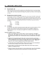
3.0 UNPACKING & INSTALLATION
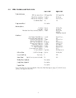
3.1
Unpacking the unit
Inspect the contents of the carton. Please notify the carrier immediately if there are any signs of damage
to the controller or its parts. Contact your distributor if any of the parts are missing. The carton should
contain: a WBL series controller and instruction manual. Any options or accessories will be incorporated
as ordered.
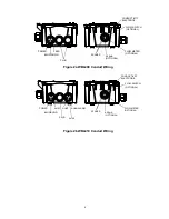
3.2
Mounting the electronic enclosure
The WBL series controller is supplied with mounting holes on the enclosure. It should be wall mounted
with the display at eye level, on a vibration-free surface, utilizing all four mounting holes for maximum
stability. Use M6 (1/4" diameter) fasteners that are appropriate for the substrate material of the wall. The
enclosure is NEMA 4X rated. The maximum operating ambient temperature is 122°F (50°C); this should
be considered if installation is in a high temperature location. The enclosure requires the following
clearances:
Top:
2"
(50
mm)
Left:
8"
(203
mm)
Right:
4"
(102
mm)
Bottom:
7" (178 mm)
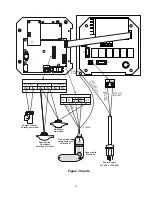
3.3 Installation
Once the WBL series controller is mounted, the metering pumps may be located at any distance from the
controller. The conductivity electrode should be placed as close to the controller as possible, to a
maximum distance of 250 ft. Less than 25 ft is recommended. The cable
MUST
be shielded from
background electrical noise. (The standard cable length is 10 feet. Should you require longer cable,
consult factory.)
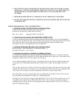
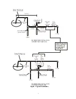
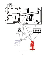
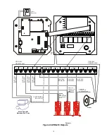
Important Installation Notes: (see figure 1)
1. Make sure the minimum water level in the boiler is at least 4-6 inches above the skimmer
blowdown line. If the skimmer line is closer to the surface, it is likely that steam will be drawn
into the line instead of boiler water. The skimmer line must also be installed above the highest
tube.
2. Maintain a 3/4 inch minimum pipe ID with no flow restrictions from the tap for the boiler
skimmer blowdown line to the electrode. If the ID is reduced below 3/4 inch, then flashing will
occur beyond that point and the conductivity reading will be low and erratic. Minimize the
usage of tees, valves, elbows or unions between the boiler and the electrode.
3. A manual shut off valve should be installed so that the electrode can be removed and cleaned.
This valve must be a full port valve in order to avoid a flow restriction.
4. Keep the distance between the tap for the boiler skimmer line to the electrode as short as
possible, to a maximum of 10 feet.
5. Mount the electrode in the side branch of a cross in a horizontal run of pipe. This will minimize
entrapment of steam around the electrode and will allow any solids to pass through.


