background image


32 

5.11 Config 

Menu 

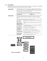
This menu allows you to export a file that contains all of the set points in the controller to a USB flash 
disk drive, and then later import the set points into another controller.  
 

Place a USB flash drive with at least 10 MB capacity into the USB port on the front panel of the 
controller. Press the Enter key to export the configuration file from the controller to the stick. The file 
name will be UCF.ini. If you are exporting files with different set points you may rename the file to 
something that describes it, as long as it has an ini extension. 

The controller will display the progress of the file download process. If the file was successfully 
exported to the USB disk the controller will display Transfer Success, otherwise Transfer Fail 1. 

Export Config 

Transfer Success 

Transfer Fail 1 

Place a USB flash drive that contains only one configuration file stored on the root directory of the 
stick into the USB port on the front panel of the controller. Press the Enter key to import the 
configuration file from the stick to the controller. The file name must have an ini extension in its 
name.  

The controller will display the progress of the file import process. If the file was successfully imported 
from the USB disk the controller will display one of the messages below: 

Import Failure 

Indicates that there were problems connecting to or accessing the USB 
stick. 

Import Success: 
Any key to reboot 

The configuration file import succeeded and will be ready for use after 
reboot. 

File Open Failed 

A config file could not be found on the USB stick or the USB stick file 
system could not be accessed. 

File Read Failed 

The config file is too short (incomplete) or empty. 

Invalid CFG File 

The imported file is not a valid config file. 

Invalid Model 

The imported config file is not for this controller model. 

Wrong SW Version 

The version of the imported config file is not compatible with this 
controller software version. 

Corrupt CFG File 

The imported config file is corrupt. (The checksum failed.) 

Import Config 

Wrong file Size 

The size of the imported config file is wrong. 


Figure 18 Config Menu 

Summary of Contents for WBL400 Series

Page 1: ...WBL400 410 Controllers WBL400 410 Series Boiler Controller Instruction Manual Walchem Corporation Five Boynton Road Hopping Brook Park Holliston MA 01746 USA TEL 508 429 1110 FAX 508 429 7433 WEB www...

Page 2: ...onics and 12 months for mechanical parts and electrodes from date of delivery from the factory or authorized distributor under normal use and service and otherwise when such equipment is used in accor...

Page 3: ...13 4 3 Keypad 14 4 4 Access Code 14 4 5 Startup 14 4 6 Shut Down 14 5 0 OPERATION 15 5 1 Main Menu 15 5 2 Conductivity Menu 17 5 3 Temperature Menu 19 5 4 Blowdown Menu 20 5 5 Feed Menu 22 5 6 Time M...

Page 4: ...industrial type with on off control outputs Timed sample or continuous modes may be selected An optional isolated 4 20 mA output that is proportional to the conductivity reading is available for all...

Page 5: ...his group must not exceed 6A Two relays for WBL400 models six relays for WBL410 models 4 20 mA optional Internally powered Fully isolated 600 Ohm max resistive load Resolution 001 of span Accuracy 1 o...

Page 6: ...mit Mode B 1 minute 99 min 59 sec Percent of Time Mode C 0 1 99 Feed Cycle Time Mode C 10 minutes 59 min 59 sec Time per Contact Mode D 1 second 59 min 59 sec Contacts by Mode D 1 contact 100 contacts...

Page 7: ...ller as possible to a maximum distance of 250 ft Less than 25 ft is recommended The cable MUST be shielded from background electrical noise The standard cable length is 10 feet Should you require long...

Page 8: ...Hour Blowdown Rate Steam Production Concentration Ratio 1 Example 3450 10 1 383 33 lbs hr 4 Determine if Continuous or Intermittent Sampling is Required Use intermittent sampling when the boiler oper...

Page 9: ...s Orifices 0 2000 4000 6000 8000 10000 12000 14000 16000 18000 10 20 30 40 50 60 70 80 90 100 200 300 Pressure PSI Lbs hr 1 8 inch dia 3 16 inch dia 1 4 inch dia 5 16 inch dia Flow Control Valve Maxim...

Page 10: ...ONDUCTIVITY ELECTRODE Cross 2 ft minimum 1 to 3 ft maximum 10 ft max with minimal valves elbows unions To Drain Skimmer Blowdown Line 3 4 Min up to Electrode Full Port Block Valve Manual Blowdown Norm...

Page 11: ...er contactor input the 4 20 mA output or a remote flow switch it is advisable to use stranded shielded twisted pair wire between 22 26 AWG Shield should be terminated at the controller ground stud see...

Page 12: ...SWITCH OPTIONAL FLOW METER OPTIONAL 4 20mA OPTIONAL SPARES Figure 2a WBL400 Conduit Wiring POWER AUX1 BLOWDOWN PLUG CONDUCTIVITY ELECTRODE FLOW SWITCH OPTIONAL FLOW METER OPTIONAL 4 20mA OPTIONAL SPAR...

Page 13: ...TR 2 IN IN FLOW SW 1 IN IN IN 5V BLK RED COND T T BLEED N C FEED N O N C N O L2 L2 L1 L2 N Hall Effect Flow Meter G R E E N W H I T E GROUND STUD SHIELD L1 L2 N G R N 1 2 0 V G R N Y E L 2 4 0 V WHT 1...

Page 14: ...O N C N O PUMP BLEED N C FEED N O N C N O L2 L2 L1 L2 N GROUND STUD BLK 120V BRN 240V WHT 120V BLU 240V GRN 120V GRN YEL 240V IF MOTORIZED BALL VALVE BLK 120 BRN 240V W HT 120V BLU 240V G R N 1 2 0 V...

Page 15: ...O N C AUX 1 N C AUX 3 N O N C N O N O ALARM N C N O GROUND STUD WHT 120V BLU 240V GRN 120V GRN YEL 240V GRN 120V GRN YEL 240V IF MOTORIZED BALL VALVE BLK 120V BRN 240V BLK 120V BRN 240V Chart Recorder...

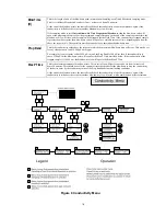
Page 16: ...sents the set point For each 1 rise above the set point a vertical bar appears to the right of the S For each 1 drop below the set point a vertical bar appears to the left of the S There are small bre...

Page 17: ...it see Section 5 9 for operation With the access code enabled any user can view parameter settings but not change them Note that this provides protection only against casual tampering Use a lock on t...

Page 18: ...unit is still controlling 5 1 Main Menu The exact configuration of your WBL controller determines which menus are available as you scroll through the settings Certain menus are only available if you...

Page 19: ...RR COND ERR NO FLOW WAITING SAMPLE HOLDING BLODWN TIMEOUT BLOWDOWN FEED TIMEOUT FEED NORMAL 1000 s 77 F 4 20 mA 9 32 mA 1000 s 77 F Access Code DIS 4 20mA menu appears only if option card is installed...

Page 20: ...above the set point a valve is opened to drop the conductivity No additional menus related to this blowdown mode are found in the Conductivity menu Sample Mode C I Intermittent Intermittent sampling...

Page 21: ...us below to determine the blowdown time Prop Band This is the conductivity value above the set point at which the maximum blowdown time will occur This may be set for any value between 1 and 10 000 S...

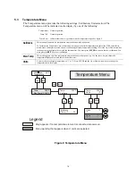
Page 22: ...arrow key to change the value displayed to match the thermometer You must press ENTER to activate the new calibration You must press the EXIT key to exit calibration Man Temp This menu appears only i...

Page 23: ...ty reading is greater than 1500 but does not turn OFF until the conductivity drops below 1300 This setting is not used when intermittent Sampling has been selected Time Limit This menu allows you to s...

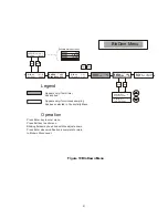
Page 24: ...djust arrows Press Enter when modification is complete to return to Blodwn Menu Level ENTER EXIT Operation NEXT PREV BloDwn Sample BloDwn Timeout Legend Appears only if limit timer has expired BloDwn...

Page 25: ...eel input has a programmable K Factor to work with a large variety of Hall Effect square wave not sine wave flow meters The Feed menu will be indicated on the display by one of the following The A ind...

Page 26: ...nes the pump on time once a given volume of water has passed through the paddlewheel sensor The volume required to initiate feed is set below Vol to Init This setting determines the volume of makeup w...

Page 27: ...ut at Hand menu Menu choices that appear when Feed as of Time mode is selected Menu choices that appear when Feed based on water contactor input is selected NEXT PREV ENTER EXIT ENTER EXIT Legend Oper...

Page 28: ...screens ENTER EXIT ENTER EXIT Output Mode FEED Output Mode ALARM Aux NO FLOW A Aux TIMEOUT A Aux LO ALRM A Aux HI ALRM A Alarm A Menu and Submenus appear only when AUX A output is configured for use...

Page 29: ...ws Time Mon 10 20 Set Time Press ENTER to set the Time Use the arrow keys to adjust the day and time and then press ENTER to store or EXIT to discard 2000 S 68 F Time Sat 12 15 Time Sat 12 15 Set Cloc...

Page 30: ...e LOW ALARM will activate If the set point is 1000 and the Low setting is 20 then the Low alarm will activate at 800 Alarm High This is the above the blowdown set point that the HIGH ALARM will activa...

Page 31: ...4 mA output from the controller Set 20mA Pt This conductivity setting will correspond to a 20mA output from the controller Calibrate This will provide fixed 4mA and fixed 20mA outputs to allow you to...

Page 32: ...Indicates that the access code is disabled No access code is required to change any setting Access Code REQ Indicates that the access code is required to alter settings Access Code OK Indicates that t...

Page 33: ...ists of time stamps of when power was lost when it was returned and the cause of the reset Current or Backup Datalog Place a USB flash drive with at least 10 MB capacity into the USB port on the front...

Page 34: ...alog Transfer Success Next Prev Datalog Copy Reset Log Next Prev ENTER EXIT ENTER EXIT ENTER EXIT Datalog Transfer Success Datalog Transfer Success Possible Status Screens Transfer Success Transfer Fa...

Page 35: ...panel of the controller Press the Enter key to import the configuration file from the stick to the controller The file name must have an ini extension in its name The controller will display the prog...

Page 36: ...le was successfully imported from the USB disk the controller will display Transfer Success The controller will automatically reboot and come up with the new software installed If the software upgrade...

Page 37: ...aned less often Cleaning Procedure The electrode can normally be cleaned using a cloth toothbrush cotton swab or paper towel and a mild detergent Occasionally an electrode may become coated with vario...

Page 38: ...will display an L at the left end of the bar graph The controller will continue to check the conductivity and feed inhibitor as programmed Possible Cause Correction Action Sensor disconnected Reconnec...

Page 39: ...ce of wire If no flow message disappears then switch or cable may be faulty Insufficient pressure drop through sample stream Check piping CAL FAIL The controller allows a maximum of 50 correction to t...

Page 40: ...Figure 3 Make sure that the correct colors go to the correct terminals and that the connections are tight Restore power and see if the conductivity is back to normal If not replace the electrode 8 0 S...

Reviews: