


The chasers are looped in on the face side according to the set angles.
Grinding with guiding presser foot :
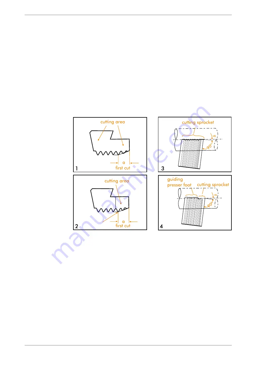
See figure 10.2 and 10.4.
The grinding process is divided in two work steps:
Grinding of the guiding presser foot:
The guiding presser foot is looped in. As grinding angle we recommend you appro-
ximately set the value of the holder angle. As cutting angle
α
value between 0° and
the selected cutting angle is set.
This isn’t of great relevance as the sprockets of the guiding presser foot don’t cut,
but are located in front of the centre of the workpiece and are used as guiding only.
Grinding of the cutting sprockets:
The selected, respectively determined angles are now exactly set.
The cutting sprockets are grinded sharply-edged up to the gap between the first and
the second complete cutting sprocket.
It is most important to cut the nook sharply-edged as when grinding the flank of the
first sprocket of the guiding presser foot, a chip pocket is formed which can lead to
cobbling of the sprocket. Moreover, it can create very uneven thread flanks.
The cutting sprockets are cut this deep that the length of the guiding presser foot
amounts to 0, 5 to 1 x lead. Please be informed that too short sprockets don’t provide
enough guidance, too long sprockets can cause chip pockets.
Please pay attention when grinding chasers for multi- start threads that the amount of
entire sprockets is at least the same as the amount of turns of the thread (i.e. should
the thread have 3 turns at least 3 entire sprockets should be grinded).
Figure 10:
Grinding of the chasers
1 Grinding
without
guiding
presser foot
2 Chaser mould
without
guiding presser foot
3 Grinding
with
guiding
presser foot
4 Chaser mould
with
guiding
presser foot
14
Operating Manual ZR 26-I
Chasers