background image

16

GM 4700AC


OPERATING MANUAL

VERSION 06/2014

ORDER NUMBER DOC2311730

4.2.3 

PRODUCT HOSES

4.2.2 

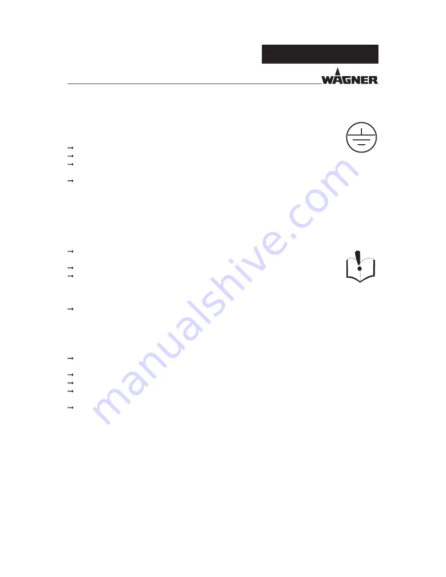
GROUNDING THE DEVICE

In order to avoid electrostatic charging of the device, the device must be grounded.
Friction, fl owing liquids, and air or electrostatic coating processes create charges. Flames 
or sparks can form during discharge.

  Ensure that the device is grounded for every spraying operation.
  Ground the work pieces to be coated.
  Ensure that all persons inside the working area are grounded, e.g. that they are wearing 

static dissipative shoes.

  Wear static dissipative gloves when spraying. The grounding takes place via the spray 

gun handle.

  Ensure that the hose material is chemically resistant to the sprayed products and the 

used fl ushing agents.

  Ensure that the product hose is suitable for the pressure generated.
  Ensure that the following information can be seen on the high-pressure hose:

 - 

Manufacturer


- Permissible operating pressure


- Date of manufacture

  Make sure that the hoses are laid only in suitable places. Hoses should not be laid in the 

following places under any circumstances:


- In high-traffic areas


- At sharp edges


- On moving parts


- On hot surfaces

  Ensure that the hoses are never run over by vehicles (e.g. fork lifts), or that the hoses are 

never put under pressure from the outside in any other way.

  Ensure that the hoses are never kinked. Observe maximum bending radii.
  Make sure that the hoses are never used to pull or move the device.
  The electrical resistance of the product hose, measured at both valves, must be less 

than 1 megohm.

  Suction hoses may not be subjected to pressure.

Several liquids have a high expansion coeffi

  cient. In some cases, their volume can rise with 

consequent damage to tubes, fi ttings, etc. and cause fl uid leakage.
When the pump sucks liquid from a closed tank, ensure that air or a suitable gas can 
enter the tank. Thus a negative pressure is avoided. The vacuum could implode the tank 
(squeeze) and can cause it to break. The tank would leak and the liquid would fl ow out.
The pressure created by the pump is a multiplication of the inlet air pressure.

Summary of Contents for GM 4700AC

Page 1: ...II 2G X Atex B_02376 AirCoat manual gun for flat and round jet nozzles Version 06 2014 Translation of the Original Operating Manual...

Page 2: ......

Page 3: ...erator 14 4 1 1 Electrical Equipment 14 4 1 2 Staff Qualifications 14 4 1 3 Safe Work Environment 14 4 2 Safety Instructions for Staff 15 4 2 1 Safe Handling of WAGNER Spray Devices 15 4 2 2 Grounding...

Page 4: ...the AirCoat Nozzle 33 7 3 5 Cleaning AirCoat Nozzle 34 7 3 6 Eliminate Nozzle Clogging 34 8 CLEANING AND MAINTENANCE 35 8 1 Cleaning 35 8 1 1 Cleaning Staff 35 8 1 2 Safety Instructions 35 8 1 3 Flush...

Page 5: ...3 1 2 Complete Nozzle Screw Joint 63 13 2 Air Caps 64 13 3 Anodized Union Nut 64 13 4 AirCoat Nozzles ACF3000 65 13 5 AirCoat Pre atomizer Nozzles ACF3000 Plus 65 13 6 Filter Insert 66 13 7 Swivel Joi...

Page 6: ...result in death or serious injury Caution a possibly hazardous situation Non observance may result in minor injury Notice a possibly hazardous situation Non observance may result in damage to property...

Page 7: ...1730 French 2311731 Dutch 2326027 Italian 2311732 Spanish 2311733 Russian 2328825 Chinese 2328826 1 4 ABBREVIATIONS Order No Order number ET Spare part Marking in the spare parts lists LA Low Air HV f...

Page 8: ...e tasks assigned to him her the potential risks associated with improper behavior as well as the necessary protective devices and measures Electrician Can assess the work assigned to him her and detec...

Page 9: ...1 WAGNER shall not accept any liability for any damage resulting from incorrect use Only use the device to work with the products recommended by WAGNER Only operate the device as a whole Do not deact...

Page 10: ...ING Hot coating products Burns Wear antistatic protective gloves When operating the device with a coating product with a temperature of 43 C 109 4 F identify the device with a warning label that says...

Page 11: ...isks Residual risk Source Consequences Specific measures Lifecycle phase Skin contact with lacquers and cleaning agents Handling of lacquers and cleaning agents Skin irritation Wear protective clothin...

Page 12: ...he permissible ambient temperature can be found in the Technical Data chapter Safe handling of WAGNER spray devices Mechanical sparks can form if the device comes into contact with metal In an explosi...

Page 13: ...ut Max T fluid 55 C 131 F J Wagner AG Altstaetten Made in Switzerland B_04161 1 2 3 4 6 5 OPERATING MANUAL VERSION 06 2014 ORDER NUMBER DOC2311730 3 3 TYPE PLATE 1 Serial No 2 Maximum air inlet pressu...

Page 14: ...ectrical safety regulations Ensure that the device is operated maintained and repaired only by trained staff Ensure that the floor in the working area is static dissipative in accordance with EN 61340...

Page 15: ...e withtheguidelinesforliquidejectiondevices ZH1 406andBGR500Part2Chapter2 29 and 2 36 If devices have been decommissioned the examination can be suspended until the next start up Carry out the work st...

Page 16: ...e of manufacture Make sure that the hoses are laid only in suitable places Hoses should not be laid in the following places under any circumstances In high traf c areas At sharp edges On moving parts...

Page 17: ...the flash point of the cleaning agent is at least 15 K above the ambient temperature or that cleaning is undertaken at a cleaning station with technical ventilation Take measures for workplace safety...

Page 18: ...Only touch hot surfaces if you are wearing protective gloves When operating the device with a coating product with a temperature of 43 C 109 4 F Mark the device with a warning label Warning hot surfa...

Page 19: ...NUMBER DOC2311730 5 DESCRIPTION Designation A Suspension hook B Regulator for shaping air C Spring cap D Trigger E Trigger locking device F Air connection G Fluid inlet H Union nut with nozzle protect...

Page 20: ...connection H for processing heated material This AirCoat manual gun is available in two different versions The choice of air cap and nozzle depends on the application therefore these components are no...

Page 21: ...r 0 8 120 8 Maximum product pressure MPa psi bar 25 3625 250 16 2320 160 Fluid inlet Inch NPSM1 4 Air connection Inch G1 4 Filter Mesh 50 100 150 200 Weight g oz 595 g 20 9 oz pH range of the product...

Page 22: ...NDITIONS Until the point of assembly the device must be stored in a dry location free of vibrations and with a minimum amount of dust The device must be stored in enclosed rooms The air temperature at...

Page 23: ...ystem The system shown in the figure is only one example of an AirCoat spraying system Your Wagner distributor would be happy to assist you in creating a spraying system solution that meets your indiv...

Page 24: ...mable vapor mixtures Risk of poisoning and burns Operate the device in a spray booth approved for the working materials or Operate the device on an appropriate spraying wall with the ventilation extra...

Page 25: ...Discharge of electrostatically charged components in atmospheres containing solvents Explosion hazard from electrostatic sparks or flames Ground all device components Ground the work pieces to be coa...

Page 26: ...ncrements using a suitable medium until the maximum pressure indicated on the type plate is reached Note Set the operating pressure to 100 bar 10 MPa 1450 psi Pull the trigger and check whether the gu...

Page 27: ...ating staff must receive appropriate training WARNING Incorrect operation Risk of injury and damage to the device If contact with paints or cleaning agents causes skin irritation appropriate precautio...

Page 28: ...event of functional faults remedy the fault as described in the Troubleshooting and rectification chapter Observe safety instructions in Chapter 4 WARNING High pressure spray jet Danger to life from...

Page 29: ...e time observe how the product is atomizing 3 Set the fluid pressure on the material pump to a point where good product atomization is achieved 4 Open the air pressure regulator for the atomizing air...

Page 30: ...object being sprayed using the shaping air regulator The illustration shows the influence of the shaping air regulator on the spraying pattern Other nozzle sizes can be mainly used to obtain larger o...

Page 31: ...s on the spraying system before moving the spraying system to another location if something must be checked on the spraying system if the nozzle or the filter is removed from the spray gun The compone...

Page 32: ...e is still not completely relieved after this If the nozzle is obstructed slowly loosen the union nut to release the residual pressure If product hose is obstructed slowly loosen the hose connections...

Page 33: ...e air cap B 5 Press AirCoat nozzle C out of air cap B by hand and treat with cleaning agent until all remaining paint has been dissolved 6 Assembly Fit AirCoat nozzle C in nozzle seal D 7 Fit air cap...

Page 34: ...nozzle guard A over the air cap B onto the spray gun and tighten by hand 8 Switch the product pressure back on 9 Turn the locking device to the spraying position and briefly pull trigger 10 When the b...

Page 35: ...during cleaning work Health hazard from inhaling solvent vapors Use of unsuitable cleaning tools and aids 8 1 CLEANING 8 1 2 SAFETY INSTRUCTIONS 8 1 1 CLEANING STAFF DANGER Exploding gas air mixture...

Page 36: ...aily The cleaning flushing agents used for cleaning or flushing must correspond with the working material Trigger guard locking device in secured position Air Product NOTICE Flushing agent in the air...

Page 37: ...on the spray gun and product pressure generator 7 Secure the spray gun with the locking device 8 Clean the spray gun body with a cleaning agent recommended by the lacquer manufacturer and dry with a...

Page 38: ...ck for leaks as described in Chapter 6 8 In accordance with the guideline for liquid ejection devices ZH 1 406 and BGR 500 Part 2 Chapter 2 29 and Chapter 2 36 The liquid ejection devices should be ch...

Page 39: ...M 4700AC OPERATING MANUAL VERSION 06 2014 ORDER NUMBER DOC2311730 8 2 3 1 GROUNDING CHECK Every day Before starting work carry out a visual check to ensure that the system is grounded 8 2 3 SAFETY CHE...

Page 40: ...hose crimping see fitting embossing 10 years from the date of the hose imprinting Fitting embossing Meaning xxx bar Pressure yymm Crimping date year month XX Internal code Hose imprinting Meaning Wag...

Page 41: ...Place the size D open end wrench on the flats of the air connection and hold it in place 5 Loosen the air hose s nut with a size C open end wrench Assembly 1 Screw on the product hose or air hose by h...

Page 42: ...the product hose together with filter housing and filter insert has been exposed push the rotary handle 66 back onto the upper filter connection 5 Pull the filter insert 64 out of the filter housing 6...

Page 43: ...s flats 13 mm 17 mm 0 51 inch 0 67 inch Procedure if connection is difficult to loosen Loosen filter housing 67 with wrench size B open end wrench supporting the filter connection with size A open end...

Page 44: ...ufacturer s instructions The nozzle is partially clogged Nozzle cleaning 7 3 5 7 3 6 The drilled holes in the air cap are damaged or clogged Clean or replace the air cap 7 3 6 Incorrectly selected air...

Page 45: ...lve rod itself is damaged Replace the entire valve rod or the individual seals 10 4 Air valve seals are leaky Replace the air valve seal 10 6 Pretension is too low Tighten up the sealing screw Gun wil...

Page 46: ...ction test in accordance with Chapter 11 In accordance with the guideline for liquid ejection devices ZH 1 406 and BGR 500 Part 2 Chapter 2 29 and Chapter 2 36 The liquid ejection devices should be ch...

Page 47: ...for carrying out the repair work on the gun described below Open end wrench SW 5 Open end wrench SW 6 Open end wrench SW 7 Open end wrench SW 13 Open end wrench SW 15 Socket wrench SW 13 Socket wrenc...

Page 48: ...essure springs 2 and 3 5 Loosen the screw 22 and remove together with the nut 20 6 Remove the trigger guard 21 7 Loosen the sealing screw 10 using a size 7 mm 0 28 inch single open end wrench 8 Carefu...

Page 49: ...seals For the assembly of the air valve seal 51 a special tool Order No 179989 is necessary 3 Screw the valve tappet 50 and cover 53 together by hand Carefully tighten in small increments with a 7 mm...

Page 50: ...h wrench in position screw the preassembled valve rod to the clamping sleeve and tighten with a size 5mm 0 20 inch open end wrench tightening torque 5 1 Nm 3 69 lbft Note reference dimension 6 Careful...

Page 51: ...51 GM 4700AC 5 2 3 4 18 19 10 10 11 12 34 50 51 53 52 20 21 B A 22 B_03650 85 5 Nm 1 3 69 lbft 12 Nm 1 8 85 lbft 87 86 87 9 mm 0 15 OPERATING MANUAL VERSION 06 2014 ORDER NUMBER DOC2311730...

Page 52: ...locking device 4 Unscrew the union nut with nozzle guard 33 5 Remove the air cap 36 together with the nozzle 13 6 Carefully release the nozzle seal 17 with the help of a screwdriver 7 Attach the new n...

Page 53: ...ive sealing ring 14 F with the help of pipe tongs or with a large screwdriver 7 Assembly attach the new distributor seal 14 F to the air cap 36 8 Place the air cap together with sealing ring 14 F into...

Page 54: ...UND JET NOZZLE Unscrew the nozzle by hand Note The sealing fitting E can be pulled out of the nozzle body using a small eye wood bolt Nozzle wrench D Order No 128901 Eject with 1 5 mm 0 06 inch pin Ho...

Page 55: ...55 GM 4700AC 55 GM 4700AC OPERATING MANUAL VERSION 06 2014 ORDER NUMBER DOC2311730...

Page 56: ...ses Examine the compatibility of the cleaning agents and working media on the basis of the safety data sheets WARNING The following tools are required for carrying out the repair work on the gun descr...

Page 57: ...the area around the hollow screw to approx 150 C 302 F 10 8 3 DISASSEMBLY 3 Loosen the hollow screw with a size SW13 0 51 inches open end wrench then remove the filter connection 4 Thoroughly clean a...

Page 58: ...e hollow screw and filter connection 2 Put the filter connection into the gun connection align and tighten the hollow screw with a tightening torque of 15 Nm 11 lbft Exceeding the allowable torque wil...

Page 59: ...59 GM 4700AC B_04160 15 Nm 11 lbft OPERATING MANUAL VERSION 06 2014 ORDER NUMBER DOC2311730 Loctite 638 Order No 2320114 Loctite 638...

Page 60: ...rigger lever can move slightly in its rest position Put the trigger lever locking device into the locking position configure the air product pressure and pull the trigger lever Neither air nor product...

Page 61: ...off Switch on atomizing air shaping air on product on Switch off product off atomizing air shaping air off 5 Flushing the gun Switch off the air and material supply open flushing valve pull trigger l...

Page 62: ...uipment must be scrapped please differentiate the disposal of the waste materials The following materials have been used Stainless steel Aluminum Elastomers Plastics Carbide Theconsumableproducts lacq...

Page 63: ...prox 250 9 84 132727 Nozzle insert R18 18 0 53 530 approx 250 9 84 132728 Nozzle insert R19 19 0 59 590 approx 250 9 84 132729 Nozzle insert R20 20 0 65 650 approx 250 9 84 132730 Nozzle insert R21 21...

Page 64: ...Designation 2313494 Air cap LV plus red for low viscosity products 2313497 Air cap HV plus blue for high viscosity products 2313498 Air cap LA plus bronze Order No Designation 2330340 Completely anodi...

Page 65: ...20 620 0 020 0 51 0 11 0 030 22 422 622 0 022 0 56 0 14 0 036 100 3 94 145 5 71 195 7 68 250 9 84 300 11 81 B_04161 OPERATING MANUAL VERSION 06 2014 ORDER NUMBER DOC2311730 13 4 AIRCOAT NOZZLES ACF300...

Page 66: ...s 2315723 Filter insert red 200 0 007 0 011 2315724 Filter insert blue 150 0 011 0 013 2315725 Filter insert yellow 100 0 013 0 019 2315726 Filter insert white 50 0 019 0 023 Order No Designation 3949...

Page 67: ...NPS 10 m 32 8 ft DN 4 ID 0 16 inch 27 MPa 270 bar 3916 psi Air G1 4 10 m 32 8 ft DN 6 mm ID 0 24 inch 1 MPa 10 bar 145 psi 2309634 AC hose set DN4 PN270 1 4 NPS 15 m PA T Material 1 4 NPS 15 m 49 2 ft...

Page 68: ...gnation 9997001 Nozzle cleaning brush 394941 Service set GM 4600 4700AC 367560 Double connector NPSM1 4 external thread for material hose extension 9985720 Double nipple G1 4 external thread for air h...

Page 69: ...ery air freight courier etc Identification in spare parts lists Explanation of column K labeling in the following spare parts lists Wearing parts Note These parts are not covered by warranty terms Not...

Page 70: ...ozzle plus see Chapter 13 5 14 1 394339 394339 Sealing ring 15 1 9974245 9974245 O ring 16 1 394922 394922 Valve housing complete 17 1 394338 394338 Nozzle seal 18 1 2312149 2312149 Collet chuck 19 1...

Page 71: ...1 86 87 53 88 36 80 29 65 68 OPERATING MANUAL VERSION 06 2014 ORDER NUMBER DOC2311730 Mounting materials Order No Designation 80 9992831 Loctite 542 81 9992833 Loctite 638 green 82 9992590 Loctite 222...

Page 72: ...63 1 132922 132922 Nozzle screw joint complete 64 1 Filter insert yellow middle 100 mesh per inch 1 2315723 2315723 Filter insert red fine 200 mesh per inch 10 pieces 1 2315724 2315724 Filter insert b...

Page 73: ...er 13 4 13 1 321xxx AC nozzle plus see Chapter 13 5 14 1 394339 Sealing ring 15 1 9974245 O ring 16 1 394922 Valve housing complete 17 1 394338 Nozzle seal 18 1 2312149 Collet chuck 19 1 394257 Valve...

Page 74: ...7 53 70 69 88 36 36 36 80 29 OPERATING MANUAL VERSION 06 2014 ORDER NUMBER DOC2311730 Mounting materials Order No Designation 80 9992831 Loctite 542 81 9992833 Loctite 638 green 82 9992590 Loctite 222...

Page 75: ...Nozzle screw joint complete 64 1 Filter insert yellow middle 100 mesh per inch 1 2315723 Filter insert red fine 200 mesh per inch 10 pieces 1 2315724 Filter insert blue middle 150 mesh per inch 10 pie...

Page 76: ...other than the address of the purchaser We do not provide warranty for damage that has been caused or contributed to for the following reasons Unsuitable or improper use faulty assembly or commission...

Page 77: ...N 13463 5 2011 DIN EN 1127 1 2011 DIN EN ISO 13732 1 2008 DIN EN 1953 2013 DIN EN ISO 4414 2010 DIN EN ISO 14462 2005 A1 2009 DIN EN ISO 4413 2010 DIN EN 13463 1 2009 Applied national technical standa...

Page 78: ...INES Part 2 Chapter 2 36 Working with Liquid Ejection Devices Part 2 Chapter 2 29 Working with Coating Products Avoiding ignition risks Painting rooms and equipment Guidelines for liquid ejection devi...

Page 79: ......
Page 80: ...r No 2311730 Edition 06 2014 Germany Phone Fax E mail Switzerland Phone Fax More contact addresses on the Internet at Company Locations WAGNER worldwide Subject to changes without notice Document No 1...

Reviews: