background image


13


material reduction/projector set cHart  / remedy in case of faults 

fc9900 Plus

10 

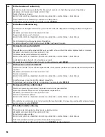
reMedy in caSe of faultS

type of malfunction


A.  Restricted air flow or no air flow


B.  Filter warning light is on


C.  The turbine has no power

  D.  Excessive arcing/sparking in the 

turbine

possible cause


1.  Air flow adjustment knob on the spray 

gun is turned off


2.  Air filters are clogged


1.  Air filters are clogged


1.  No power at the power supply


2.  Circuit breaker has been tripped.


3.  Worn turbine brushes


1.  Worn turbine brushes


2.  Damaged commutator

Measures for eliminating the malfunction


1.  Adjust the air flow adjustment knob


2.  Clean or replace the filters


1.  Clean or replace the filters


1.  Check the power supply


2.  Reset the breaker.  If problem persists, have turbine 

inspected at an authorized Wagner service center.


3.  Have the brushes replaced at an authorized Wagner 

service center


1.  Have the brushes replaced at an authorized Wagner 

service center


2.  Replace the turbine (contact a Wagner service technician)

i

The turbine motor can be damaged if not serviced properly.  Have the brushes (P/N 0276878) checked for wear by an 

authorized service center every 400 hours.
Clean filters regularly.  Clogged filters can cause excessive heat and possibly damage the unit.
For additional troubleshooting information, see the manual that came with your gun.

10.1 

Service

Should your spray system need service during the warranty period, return your unit and the proof of purchase to the distributor 

where it was purchased.  At our option, the unit will be repaired or replaced.  In a continued commitment to improve quality, we 

reserve the right to make component or design changes when necessary.

Material reduction/projector Set chart

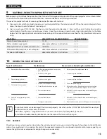
Before spraying, the material being used must be thinned with an appropriate solvent and the proper projector set must be installed.  

It is always best to follow the material manufacturers recommendations and thinning procedures.
There are two simple methods of measuring the proper thickness of a material:

1. 

Dip a paint stick into the material and remove it, watching carefully as the material runs off.  When the material begins to form 

drops, the drops should fall about 1 second apart.

2. 

Use a viscosity cup (P/N 0153165).  Dip the cup into the material and remove it.  Use a watch or clock to time how long the 

material drains from the cup in a continuous stream.  Once the continuous stream breaks, stop timing and refer to the table 

below.  Add the appropriate solvent and continue testing until the proper thickness is reached for the type of material you are 

using.

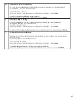
Material

viScoSity din-S (4 MM din cup)

projector Set

Solvent-based lacquer paints

15 - 45

3 - 4

Water-soluble lacquer paints

observe manufacturer’s instructions

4 - 5

Wood preservatives (scumble, mordants, etc).

undiluted

2 - 3

Multi-color effect materials, multi-color paint

observe manufacturer’s instructions

6 - 7

Texture and effect paints

observe manufacturer’s instructions

5 - 6

Summary of Contents for FC9900 Plus

Page 1: ...finecoat 9900 Plus HVLP spray system owner s manual betriebsanleitung Mode d emploi Istruzioni per l uso MANUAL DE OPERA ES Instrucciones de uso I GB E F RFB D 0618 Form No 0276799B wagner group com...

Page 2: ...____________11 8 Choosing a projector set_____________ 12 8 1 Changing a projector set________________________12 9 Material reduction projector set chart_________________________________ 13 10 Remedy...

Page 3: ...ated hydrocarbon solvents such as methylene chloride and 1 1 1 trichloroethane They are not compatible with aluminum and may cause an explosion If you are unsure of a material s compatibility with alu...

Page 4: ...moke in spray area Fire extinguisher must be present and in good working order Power cord must be connected to a grounded circuit electric units only Follow material and solvent manufacturer s warning...

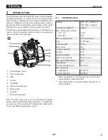
Page 5: ...er switch 8 Air outlet Air hose not pictured With this HVLP spray system you can achieve the highest quality professional finish possible with little or no preparation or setup time Please review all...

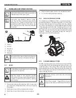
Page 6: ...et on your spray gun 4 Plug the turbine power cord into a grounded receptacle 5 Turn on the turbine and begin spraying 3 2 Dual Filtration System The turbine has two different air filters one for atom...

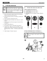
Page 7: ...ainer onto the spray gun and secure with the closing lever 6 Switch the turbo blower on 7 Point the paint spray gun at the object to be sprayed 8 Determine the settings for the spray pattern spray jet...

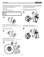
Page 8: ...turning the material adjustment knob Turn to the left more material Turn to the right less material Setting the amount of air fig 8 The correct setting for the amount of air is decisive for the atomi...

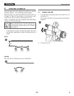
Page 9: ...from the object and avoid stopping spraying whilst still on the object i If the round jet setting is used the distance may be increased according to the size of the object being sprayed In case of exc...

Page 10: ...ompletely Never leave solvents in the spray gun container this may cause pressure to build up in the container Always keep the paint container seal clean of left over coating material and check regula...

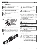
Page 11: ...essurized air to blow out the contaminants For material that is not blown or knocked loose easily soak the filters in soapy water or mineral spirits Allow the filters to dry completely before placing...

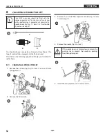
Page 12: ...ype of material to be sprayed and the finish desired The chart on the following page should help you to make the right choice 8 1 Changing a projector set 1 Remove the air cap ring Fig 18 item 1 air c...

Page 13: ...d service during the warranty period return your unit and the proof of purchase to the distributor where it was purchased At our option the unit will be repaired or replaced In a continued commitment...

Page 14: ...lls Material supply by means of a commercially available pressure tank Part No 0261 023 WSL 60 Spray lance fig 24 When coating materials can be used Coating materials which due to their properties can...

Page 15: ...ee claims must be made immediately or at the latest within a period of 2 weeks The authorised specialist shop that delivered the device is entitled to accept guarantee claims Guarantee claims may also...

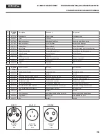
Page 16: ...e turbine 5 tapes 100V 110V voir la liste s par e 5 Stage turbine assembly 220V 240V see separate listing 5 stufige Turbinenanordnung 220V 240V siehe separates Verzeichnis Ensemble turbine 5 tapes 220...

Page 17: ...lsa Conjunto de turbina de 5 etapas 220V 240V consulte la lista separada 3 0524927 Silenziatore lato parete Silenciador lateral Silenciador de la pared lateral 4 0524593A Assemblaggio del silenziatore...

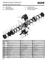
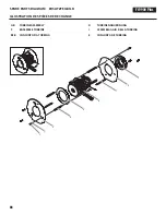
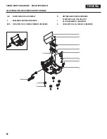
Page 18: ...Ersatzteilbild Illustration des pi ces de rechange FC9900 Plus GB turbine assembly D TURBINENANORDNUNG F ENSEMBLE TURBINE I ASSEMBLAGGIO DELLA TURBINA RFB CONJUNTO DA TURBINA E CONJUNTO DE TURBINA 88...

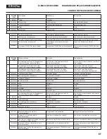
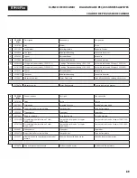
Page 19: ...r 0276878 Motor brush kit Motor B rstensatz Trousse de brosse moteur FC9900 Plus Denominazione Descri o Denominaci n 1 9810108 Dado Porca Tuerca 2 9821503 Fermadado Arruela de fixa o Arandela de segur...

Page 20: ...andle Unterer Griff Poign e inf rieure 6 9802266 Screw Schraube Vis 7 0524963 Lock washer Unterlegscheibe Rondelle Grower 8 0524553 Switch Schalter Commutateur 9 0529549 Circuit breaker switch kit 15A...

Page 21: ...ad 8 0524553 Commutatore Interruptor Interruptor 9 0524549 Kit per l interruttore di circuito 15 A 100V 110V Kit do interruptor do disjuntor 15 A 100V 110V Kit del conmutador del interruptor autom tic...

Page 22: ...de rechange FC9900 Plus GB lower housing assembly D UNTERE GEH USEANORDNUNG F ENSEMBLE BO TIER INF RIEUR I ASSEMBLAGGIO DEL VANO DI ALLOGGIAMENTO INFERIORE RFB CONJUNTO DO COMPARTIMENTO INFERIOR E CON...

Page 23: ...chraube Vis FC9900 Plus Denominazione Descri o Denominaci n 1 0277278 Protezione dell acqua Protetor de gua Protector de agua 2 9805387 Vite Parafuso Tornillo 3 0277443 Coperchio della cassetta di spu...

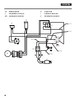
Page 24: ...900 Plus GB wiring diagram D SCHALTPLAN F DIAGRAMME DU C BLAGE I SCHEMA DI CABLAGGIO RFB DIAGRAMA DE CONEX ES E DIAGRAMA DE CABLEADO 94 1 2 3 4 6 5 0276859 0276860 0276863 0276862 0524598 9850577 0276...

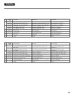
Page 25: ...277472 Commutatore del flusso d aria Interruptor de fluxo de ar Interruptor del flujo de aire 5 Cavo di alimentazione Cabo de energia Cable de alimentaci n 6 Turbina Turbina Turbina FC9900 Plus Descri...

Page 26: ...E est jointe ce produit Elle peut tre command e au besoin sous le num ro de commande 2389561 I Dichiarazione di conformit UE Dichiariamo sotto la nostra esclusiva responsabilit che il presente prodott...

Page 27: ...nt 2006 42 EG 2014 30 EU 2011 65 EU 2012 19 EU Anv nta harmoniserade normer EN ISO 12100 EN 1953 EN 60204 1 EN 61000 3 2 EN 61000 3 3 EN 61000 6 1 EN 61000 6 3 EU konformitetsf rklaringen medf ljer pr...

Page 28: ...ement nous Indicazione per lo smaltimento Secondo la direttiva europea 2002 96 CE per lo smaltimento di vecchi apparecchi elettrici e la sua conversione nel diritto nazionale questo prodotto non va sm...

Page 29: ...de Ratingen J Wagner GmbH Service St tzpunkt Siemensstra e 6 10 40885 Ratingen Tel 0 21 02 3 10 37 Telefax 0 21 02 3 43 95 N rnberg Grimmer GmbH Starenweg 28 91126 Schwabach Tel 0 91 22 7 94 73 Telef...

Page 30: ...Wagner International AG Industriestrasse 22 9450 Altst tten Schweiz Tel 41 71 7 57 22 11 Telefax 41 71 7 57 22 22 wagner wagner group ch F Euromair Antony S A V Ile de France 12 14 av F Sommer 92160...

Reviews: