


PT 6L
Schematics
wc_tx001596gb.fm
55
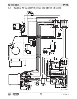
7.3
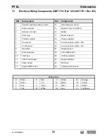
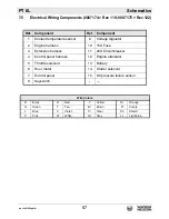
Electrical Wiring Components (0007174 < Rev 120; 0007175 < Rev 123)
Ref. Component
Ref. Component
1
Cylinder head temperature switch
14
Oil temperature sensor
2
Engine harness
15
Engine Control Unit (ECU)
3
Extension harness
16
Battery
4
Glow plug
17
Starter solenoid
5
Throttle solenoid
18
Voltage regulator
6
Hour meter
19
Low oil pressure switch - N.O.
7
Control panel
20
Low oil pressure switch - N.C.
8
Keyswitch
21
Diagnostic port
9
Glow plug relay
22
Cam RPM sensor
10
15A Fuse
23
Control solenoids
11
20A Circuit breaker
24
Engine alternator
12
Pump sensor
25
80A Fuse
13
Engine RPM sensor
26
Control panel harness
Wire Colors
B
Black
R
Red
Y
Yellow
Or
Orange
G
Green
T
Tan
Br
Brown
Pr
Purple
L
Blue
V
Violet
Cl
Clear
Sh
Shield
P
Pink
W
White
Gr
Gray
LL
Light blue
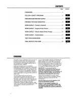
Summary of Contents for PT 6L
Page 1: ...0154629en 008 0810 0 1 5 4 6 2 9 E N Operator s Manual Pump PT 6L ...
Page 8: ...8 wc_bo0154629en_008TOC fm Table of Contents PT 6L ...
Page 33: ...PT 6L Operation wc_tx001597gb fm 33 wc_gr003210 3 1 2 e g 3 1 2 d a b c f ...
Page 52: ...Technical Data PT 6L 52 wc_td000099gb fm 6 5 Dimensions wc_gr001154 ...
Page 58: ......
Page 59: ......
Page 60: ......
Page 61: ......
Page 62: ......
Page 63: ......
Page 64: ......
Page 65: ......
Page 66: ......
Page 67: ......
Page 68: ......
Page 69: ......
Page 70: ......
Page 71: ......


