


G 150 / 180 / 240
Schematics
wc_tx000879gb.fm
65
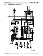
5.2
DC Schematic Components
Ref.
Description
Ref.
Description
1
Electronic control board
19
Remote start
2
Engine outputs
20
Emergency stop switch
3
Engine sensor inputs
21
Toggle switch
4
Emergency stop
22
10A fuse
5
Cold crank delay
23
Main breaker
6
Remote start
24
Lug door safety switch
7
Fuel level
25
Mechanical lugs
8
Battery -
26
Relay (if equipped)
9
B
27
Intake heater (if equipped)
10
Crank
28
Starter relay
11
Run / fuel
29
Starter
12
Remote annunciator
30
Alternator
13
21 position connector
31
12V battery
14
Start relay
32
Battery disconnect switch
15
Alternator / charge
33
John Deere engine ECU
16
B+ switched
34
Engine harness
17
Crank delay
35
Terminal block
18
Fuel level
36
Resistor (if equipped)
Summary of Contents for G 150
Page 1: ...Mobile Generator G 150 G 180 G 240 OPERATOR S MANUAL 0171953en 003 0709 0 1 7 1 9 5 3 E N ...
Page 2: ......
Page 4: ...Foreword G 150 180 240 wc_tx000869gb fm 4 ...
Page 12: ...Safety Information G 150 180 240 wc_si000265gb fm 12 wc_si000265gb fm 12 1 6 Label Locations ...
Page 13: ...G 150 180 240 Safety Information wc_si000265gb fm 13 wc_gr005517 G H J R GG FF R A H K ...
Page 63: ...Factory Installed Options wc_tx000880gb fm 63 Notes ...


