background image

Summary of Contents for DW100

Page 1: ...5 1 0 0 0 1 5 3 6 3 Operator s Manual Dumpers DW60 DW90 DW100 Machine type D18 01 D18 02 D18 03 Edition 1 1 Order no 5100015363 Language us...

Page 2: ...chnical data dimensions and weights are only given as an indication Non metric weights and measurements are approximate Responsibility for errors or omissions not accepted The cover features the machi...

Page 3: ...o operation 4 1 Cabin control stand 4 1 4 2 Overview of control elements 4 17 4 3 Indicator lights and warning lights overview 4 24 4 4 Preparatory work 4 29 4 5 Starting and stopping the engine 4 34...

Page 4: ...Braking system 7 39 7 18 Tires 7 40 7 19 Maintenance of attachments 7 41 7 20 Maintenance of options 7 41 7 21 Exhaust gas treatment 7 42 7 22 Machine preservation 7 48 8 Malfunctions 8 1 Engine warni...

Page 5: ...Fachausschuss Bauwesen Landsberger Str 309 80687 Munich Germany Distinguishing EU number 0515 Notified body involved in procedure T V S D Industrie Service GmbH Westendstr 199 D 80686 Munich Directive...

Page 6: ...erungsstelle Fachausschuss Bauwesen Landsberger Str 309 80687 Munich Germany Distinguishing EU number 0515 Notified body involved in procedure T V S D Industrie Service GmbH Westendstr 199 D 80686 Mun...

Page 7: ...ierungsstelle Fachausschuss Bauwesen Landsberger Str 309 80687 Munich Germany Distinguishing EU number 0515 Notified body involved in procedure T V S D Industrie Service GmbH Westendstr 199 D 80686 Mu...

Page 8: ...erungsstelle Fachausschuss Bauwesen Landsberger Str 309 80687 Munich Germany Distinguishing EU number 0515 Notified body involved in procedure T V S D Industrie Service GmbH Westendstr 199 D 80686 Mun...

Page 9: ...ierungsstelle Fachausschuss Bauwesen Landsberger Str 309 80687 Munich Germany Distinguishing EU number 0515 Notified body involved in procedure T V S D Industrie Service GmbH Westendstr 199 D 80686 Mu...

Page 10: ...erungsstelle Fachausschuss Bauwesen Landsberger Str 309 80687 Munich Germany Distinguishing EU number 0515 Notified body involved in procedure T V S D Industrie Service GmbH Westendstr 199 D 80686 Mun...

Page 11: ...ference for experienced personnel This is why the Operator s Manual must be kept at hand in the machine The operator must carefully read and understand the Operator s Manual before starting up servici...

Page 12: ...an alphabetical list B Continuation of an alphabetical list Cross references see page 1 1 page Cross references 7 pos no or table no Cross references fig 3 fig no 1 Cross references see chapter 5 Ope...

Page 13: ...approximately PCM particulate matter catalysts FGPS Front Guard Protective Structure FOPS Falling Objects Protective Structure if nec if necessary max maximum min minimum Pos Position ROPS Roll Over...

Page 14: ...erm machine refers to the dumpers described in this Operator s Manual Machine operation All work for example machine travel moving material daily maintenance an operator is allowed to or has to perfor...

Page 15: ...ements for safe operation Among other things safe machine operation depends on the following points Machine model and equipment Machine maintenance Work and travel speed Nature of ground and work envi...

Page 16: ...olume unit 1 cm 0 061 in 1 m 35 31 ft 1 ml 0 034 US fl oz 1 l 0 26 gal 1 l min 0 26 gal min Unit of length 1 mm 0 039 in 1 m 3 28 ft Weight 1 kg 2 2 lbs 1 g 0 035 oz Pressure 1 bar 14 5 psi 1 kg cm 14...

Page 17: ...used by these modifications shall not be appli cable The safety of the machine can be negatively affected by performing machine modifications without proper authority and by using spare parts equipmen...

Page 18: ...1 8 BA D18 us 1 1 D18v100 fm 1 Foreword Notes...

Page 19: ...ed Consequences in case of non observance Avoidance of injury or death WARNING WARNING identifies a situation that can cause death or serious injury if it is not avoided Consequences in case of non ob...

Page 20: ...d and repaired only by a Wacker Neuson service center Required knowledge of operator The operator is responsible for other persons Avoid any operational mode that might be prejudicial to safety The sp...

Page 21: ...into operation or operate a damaged or malfunctioning machine If a damage or malfunction occurs during operation put the machine out of operation immediately and secure it against restart Have all mal...

Page 22: ...te the machine only with the seat belt fastened and only from the place provided for this Check the condition and the fastening of the seat belt Have malfunc tioning seat belts and mounting hardware r...

Page 23: ...In conditions of darkness and poor visibility switch on existing work lights and ensure that motorists are not blinded by these lights If the existing lights of the machine are not sufficient for perf...

Page 24: ...ights Do not use any liquid or gaseous starting aids for example ether or starting fuel Machine operation Start and operate the machine only with the seat belt fastened and only from the place provide...

Page 25: ...e for example the registration documents The attachment fitted onto the machine must be empty and in transport position The attachment fitted onto the machine must be equipped with the mandatory light...

Page 26: ...ing and removing a load Wear protective clothing and equipment when fastening guiding and removing loads for example a hard hat safety glasses protective gloves safety boots Do not place lifting and f...

Page 27: ...r the load Stop the machine immediately and stop the engine if persons enter the danger zone Use the machine for lifting gear applications ONLY if the mandatory lifting gear for example a joint rod an...

Page 28: ...ipment works correctly for example the brakes lights Before starting machine travel ensure that nobody is between the machine and the trailer 2 7 Attachment operation Attachments Use only attachments...

Page 29: ...achment to the ground 2 8 Towing loading and transporting Towing Seal off the danger zone Ensure that no one is near the towing bar or cable The safety distance is equal to 1 5 times the length of the...

Page 30: ...within sight or sound of him Observe all movements of the machine and lifting gear Secure the machine against unintentional movement Raise the machine only after it is safely attached and the person a...

Page 31: ...hines of the German employers liability insurance association for construction engineering Bear in mind the weather conditions for example ice snow Ensure the minimum load on the steering axle s of th...

Page 32: ...Both persons must be authorized and trained for the operation of the machine One person must be seated on the operator seat and stay in contact with the second person Keep a safe distance from rotati...

Page 33: ...med under a raised machine attachment support the machine attachment for example with a lift platform trestles ensuring safety and stability Hydraulic cylinders or jacks alone do not sufficiently secu...

Page 34: ...e parts Protective structures The cabin rollbar and protective screen are tested protective structures and may not be modified for example no drilling bending welding Perform a visual check according...

Page 35: ...ittings regularly for leaks and visible damage Splashed oil can cause injury and fire Leaking hydraulic and compressed air lines can cause the full loss of the brake effect Have damage and leaks immed...

Page 36: ...LIFORNIA Proposition 65 Warning Engine exhaust some of its constituents and certain vehicle components contain or emit chemicals known to the State of California to cause cancer and birth defects or o...

Page 37: ...le detergents Keep the area around the exhaust system free of flammable materials Due to hot machine parts maintain a safe distance from easily flammable material for example from hay dry leaves Stop...

Page 38: ...Have damaged sound baffles immediately replaced for example an insulating mat muffler Before starting work get informed on the noise level of the machine attachment for example on the adhesive label...

Page 39: ...mbolic representations 1 2 3 6 5 7 8 9 11 10 4 No Designation No Designation 1 Rear chassis 7 Rollbar 2 Front chassis 8 Control stand 3 Tilt cylinder 9 Skip 4 Mudguard 10 Steering cylinder 5 Engine co...

Page 40: ...12 13 14 No Designation No Designation 1 Rear chassis 8 Skip 2 Front chassis 9 Tilt cylinder 3 Articulated joint 10 Steering cylinder 4 Operator seat 11 Swivel centring 5 Control stand 12 Swiveling c...

Page 41: ...skip or swivel skip option Rollbar or cabin option Four cylinder Perkins diesel engine 55 kW 62 5 kW 86 kW Articulated machine 2 rigid axles Permanent 4 wheel drive Information The machine can be equ...

Page 42: ...g triangle with design certification 1 warning light with design certification 1 first aid kit in accordance with the legal regulations of your country Driving license Earth moving machinery may be dr...

Page 43: ...n lead to situations with serious injury or death Do not remove warning and information labels Immediately replace damaged warning and information labels Information Type quantity and position of the...

Page 44: ...ne serial number Fahrzeug Modell model mod le Machine designation Leistung performance Engine power Typ version Machine model Betriebsgewicht operating weight poids en charge Operating weight Transpor...

Page 45: ...7 Introduction 3 Rollbar type label The type label is located on the right on the rollbar Cabin type label option The type label is located on the B pillar on the left Fig 7 symbolic representation Fi...

Page 46: ...3 8 BA D18 us 1 1 D18e300 fm 3 Introduction Warning labels Fig 9...

Page 47: ...S bar on the left Meaning Read the Operator s Manual before starting the machine Remove the starting key and carry it with you Injury hazard due to rotating parts Open the maintenance flap only at eng...

Page 48: ...tion Near the center pivot prop and the maintenance prop of the skip Meaning Do not use starting aid sprays Position On the outside left of the engine cover Meaning Distance articulation range Keep a...

Page 49: ...d turning the skip swivel skip option Position On the right beside the operator seat Meaning Machine operation is only allowed if the rollbar is raised and locked and if the seat belt is fastened Posi...

Page 50: ...3 12 BA D18 us 1 1 D18e300 fm 3 Introduction Information labels Fig 20...

Page 51: ...points Position At the lifting eyes Meaning Machine tie down points Position At the tie down points Meaning Only refuel with diesel fuel with a sulfur content of less than mg kg als15 0 0015 Position...

Page 52: ...n the machine Position On the rear frame on the right Meaning This label explains how to lift the machine with a crane Position At the rear of the skip Meaning Indication of maintenance intervals Posi...

Page 53: ...Meaning This label shows the following information regulations Maximum payload of machine Tilt out the raised skip only on horizontal ground Tilt out only in straight machine position Maximum slope in...

Page 54: ...3 16 BA D18 us 1 1 D18e300 fm 3 Introduction ANSI label option Fig 36...

Page 55: ...ction 3 Position On the air filter in the engine compartment Position On the B pillar cabin or on the ROPS bar on the right Position On the air filter in the engine compartment Position At the rear of...

Page 56: ...3 18 BA D18 us 1 1 D18e300 fm 3 Introduction Position On the battery cover Position On the battery cover Position On the skip on the left and right Fig 41 Fig 42 Fig 43...

Page 57: ...BA D18 us 1 1 D18e300 fm 3 19 Introduction 3 Position On the B pillar on the left Position On the B pillar on the left Fig 44 Fig 45...

Page 58: ...3 20 BA D18 us 1 1 D18e300 fm 3 Introduction Position On the B pillar on the left Position On the inside of the engine cover Position On the maintenance flap on the left and right Fig 46 Fig 47 Fig 48...

Page 59: ...Introduction 3 Position On the maintenance flap on the left Position On the B pillar cabin or on the ROPS bar on the right Position On the machine frame on the left and right Position On the ROPS bar...

Page 60: ...3 22 BA D18 us 1 1 D18e300 fm 3 Introduction Notes...

Page 61: ...y Do not operate the machine CAUTION Crushing hazard due to unlocked cabin door Unlocked cabin doors can cause crushing Lock the cabin door Use the handholds for closing Entry and exit Use the climbin...

Page 62: ...nlocking Turn the starting key in door lock A anticlockwise L Lock Turn the starting key in door lock A clockwise R Opening the door Outside Press door lock A and pull handle B To keep the door in the...

Page 63: ...se it with handle C until it engages Opening the door to a gap The door can be opened to a gap during machine operation with the door arresters at the front left and right in the cabin 1 Turn door ope...

Page 64: ...on Machine operation is prohibited for operators weighing less than 50 kg 110 lbs or more than 140 kg 309 lbs Information The operator seat can be fitted with an optional operator presence switch The...

Page 65: ...dicating instrument B on the seat surface Adjusting the backrest 1 Sit down on the operator seat 2 Push handle C in the direction of the arrow and move the backrest to the required position at the sam...

Page 66: ...over hard edged or fragile items in your clothes Ensure that the buckle is inserted pull test Do not use seat belt extensions WARNING Injury hazard due to damaged or dirty seat belt A damaged or dirt...

Page 67: ...machine This can cause accidents with serious injuries or death Adjust the existing visual aids for example the rearview mirrors correctly Interrupt work immediately if persons enter the danger zone...

Page 68: ...he national and regional regulations Use safety oriented ladders and work platforms for adjustment work on the machine Do not use machine components as a climbing aid Set the skip to travel position b...

Page 69: ...following settings can be made Brightness Contrast Color Color 1 Press the Menu button 2 Select the required setting with the buttons 3 Press the SEL button 4 Select the required setting with the but...

Page 70: ...lable from Wacker Neuson Contact a Wacker Neuson service center for the installation of a fire extinguisher NFPA Information Ensure that the fire extinguisher is firmly fastened during machine operati...

Page 71: ...rmed by a Wacker Neuson service center Replace self locking fasteners Screws to which an adhesive has been applied must be cleaned with a suitable cleanser before they are re used Information Machine...

Page 72: ...falling objects Information The cabin complies with the FOPS level II requirements according to EN ISO 3449 2008 The machine owner must ensure that the hazard situation is evaluated and that the natio...

Page 73: ...ance through a passage DANGER Accident hazard during machine operation with a lowered rollbar Can cause serious injury or death Perform machine travel only on absolutely level ground Do not fasten the...

Page 74: ...fied person 3 Secure the rollbar with lock pins B 4 Secure lock pins B with split pins C 5 Lower ring D Sun visor option The sun visor can increase road safety It is located at the upper edge of the c...

Page 75: ...con 2 Route the cable for the rotating beacon through the opening in the roof 3 Insert the assembly brackets D through the openings in the roof and tighten screws E to 87 Nm 64 ft lbs 4 Insert extensi...

Page 76: ...he skip grid on the assembly points with at least two persons Use suitable external climbing aids 3 Tighten the four screws B to 410 Nm 302 ft lbs Lowering raising the skip grid The skip grid must be...

Page 77: ...ted beside the starter 4 2 Overview of control elements This chapter describes the controls and contains information on the function and handling of the indicator lights and controls The pages stated...

Page 78: ...4 18 BA D18 us 1 1 D18i400 fm 4 Putting into operation Control stand Fig 85 Overview of control elements 4 5 6 1 2 9 10 3 11 8 7...

Page 79: ...elt 4 4 4 6 2 Service brake 5 4 3 Steering column lever option for Austrian road traffic regulations StVZO 4 22 4 Display element 4 24 5 Switch panel 4 22 6 Accelerator pedal 5 3 7 12 V connection 4 1...

Page 80: ...4 20 BA D18 us 1 1 D18i400 fm 4 Putting into operation Cabin option Fig 86 Overview of control elements 7 15 8 9 1 5 12 13 6 14 3 4 16 17 11 2 10...

Page 81: ...2 5 Service brake 5 4 6 Steering column lever option for Austrian road traffic regulations StVZO 4 22 7 Display element 4 24 8 Switch panel 4 22 9 Accelerator pedal 5 3 10 12 V connection 4 17 11 Docu...

Page 82: ...nto operation Control elements and switches Fig 87 Switch panel on left option Switch panel 2 10 8 Rear left switch panel option 1 3 4 12 11 6 7 Front side of control lever 9 Steering column lever opt...

Page 83: ...Particulate matter catalyst Tier IV engine only 7 42 5 Operating hydraulics 5 22 6 Selection of travel direction 5 11 7 Eco push button 5 3 8 Speed changeover no function for DW 60 5 3 9 Horn 5 18 10...

Page 84: ...play informs the operator of the operating states required maintenance or possible machine malfunctions Information After switching on the starter the indicator lights are checked during the first 2 s...

Page 85: ...5 Yellow Engine warning 8 1 8 2 7 48 6 Yellow PCM regeneration 7 42 7 Red Engine oil pressure 8 2 8 Yellow Preheating 4 35 9 Red Charge indicator light 8 2 10 Red Parking brake 5 4 11 Red Coolant temp...

Page 86: ...ing hours to next maintenance Time 5 7 Engine speed Fuel tank capacity 4 28 Coolant temperature 8 2 8 4 Engine error 8 6 Machine error Engine data Machine data Particulate matter catalyst without excl...

Page 87: ...of display contrast Setting of time date Pilot control pressure 8 2 Replace the hydraulic oil filter Dirty air filter Dirty hydraulic oil radiator Charge indicator light PCM low load 7 42 PCM medium l...

Page 88: ...down to 0 0 hours The wrench symbol then starts to flash The maintenance meter keeps on counting down 0 1 hours 0 2 hours etc Information After 500 operating hours the output of the Tier IV diesel en...

Page 89: ...me Wacker Neuson recommends trying out the machine on open ground without any obstacles When using the machine check the surroundings constantly in order to identify potential hazards in time Before s...

Page 90: ...an see chapter 7 2 Maintenance overview on page 7 2 Face the machine as you enter and exit it and only use the mandatory climbing aids for entering and exiting Keep the footholds and the handholds cle...

Page 91: ...e 1 Enough fuel in the tank 7 20 2 Correct engine oil level 7 26 3 Coolant level OK 7 28 4 Hydraulic oil level correct 7 33 5 Correct brake fluid level 7 39 6 Glass cleaner in washer reservoir OK 7 39...

Page 92: ...8 2 3 Has a brake test been performed 5 5 4 Coolant temperature of engine in normal range 8 2 8 4 5 Indicator lights for hydraulic oil filter and air filter do not illuminate 8 2 6 Does the control l...

Page 93: ...upt acceleration braking and changing travel direction Do not run the engine at high speed for extended periods Observe the maintenance plans see chapter 7 2 Maintenance overview on page 7 2 Equipment...

Page 94: ...hydraulics on page 5 10 4 5 Starting and stopping the engine Preparations for starting the engine WARNING Accident hazard due to unintentional operation of the machine Unintentional operation can caus...

Page 95: ...ut If the engine does not start after 30 seconds Interrupt the start procedure and repeat it after two minutes If the engine still does not start after a few tries contact a Wacker Neuson service cent...

Page 96: ...e After reaching the operating temperature the engine can be operated under full load The engine reaches its operating temperature more quickly at low engine speed and under load This is more efficien...

Page 97: ...rotective equipment WARNING Injury hazard due to rotating parts Rotating parts can cause serious injury or death Open the maintenance flap only at engine standstill NOTICE Damage to machine due to ele...

Page 98: ...fety requirements Connections 1 Move vehicle Y close to machine X so that the length of the battery jumper cables is sufficient 2 Let the engine of vehicle Y run 3 Remove rubber mat A 4 Remove screws...

Page 99: ...little WARNING Injury hazard due to open base cover Can cause serious injury and death Ensure a secure footing when you get on the machine with the base cover open 9 Start the engine of machine X 10 D...

Page 100: ...t regeneration cycles only in case of Tier IV Reduced engine oil replacement intervals Stopping the engine NOTICE Possible damage to the engine when it is stopped after running under high load Letting...

Page 101: ...panel cover B until it locks into place Leave instrument panel cover B open during operation To lock instrument panel cover B disengage it from the lock close it and lock it with ball handle C Tarp op...

Page 102: ...axle but with the steering joint Emergency steering features The machine can still be steered if the engine or the pump unit breaks down however this requires more muscle strength Take this into accou...

Page 103: ...anges that can be selected with push button A on the control lever The Eco mode is selected with push button B Fuel saving operation is selected with this mode and maximum speed is reduced see Maximum...

Page 104: ...device during machine travel Can cause serious injury or death Use the parking brake only at machine standstill The parking brake may be used briefly in case of a service brake malfunction Pull the p...

Page 105: ...longer than 30 seconds The machine automatically disables the traveling drive after 30 seconds if the parking brake is applied 1 Lower the skip 2 Apply the parking brake 3 Start the machine 4 Set the...

Page 106: ...0 fm 5 Operation Multifunctional display Display element buttons A selection button B to next menu page set Menu structure of display setting Information The software version number is displayed from...

Page 107: ...elected menu level is marked with an arrow Press push button A 1 x brightness Press push button A 2 x contrast Press push button A 3 x time date Adjusting brightness Press push button B to access the...

Page 108: ...ast Setting the time or date Adjustment sequence year month day hours minutes Press push button B to access the adjustment mode Press push button A to set or to access the next setting month day etc P...

Page 109: ...ore starting machine travel WARNING Accident hazard due to machine rolling away under its own weight Can cause serious injury and death Change over the travel direction only if the machine is at a sta...

Page 110: ...If the machine is equipped with a swivel skip ensure that it is in the middle position Enabling disabling the operating hydraulics Fig 115 Fig 116 Fig 117 A 1 2 Function Position Disables the operatin...

Page 111: ...d reverse control C to the required position before starting machine travel 1 Neutral position 2 Forward 3 Reverse Release the parking brake Press the accelerator pedal Machine travel starts Stopping...

Page 112: ...ot turn or tilt out a full skip during uphill or downhill machine travel Tilt out the skip on slopes only on the uphill side of the machine Diagonal machine travel is prohibited Stones and the humidit...

Page 113: ...machine travel on slopes steeper than 25 l Machine travel on slopes with an unloaded skip When performing machine travel on slopes with an unloaded skip the front side of the machine must always face...

Page 114: ...across slopes Do not perform machine travel on slopes with a lateral angle of inclination over 25 Change position on level ground and then perform straight ahead machine travel onto the slope Diagonal...

Page 115: ...e machine accordingly for example with chocks 1 Park the machine on firm level and horizontal ground The machine may be parked on a slope only if it cannot be avoided Park the machine only transversel...

Page 116: ...ob site can be ensured without blinding other motorists Information Turn on the working lights in conditions of poor visibility If illumination still is not sufficient use external lights If this stil...

Page 117: ...light option Switch A is located on the interior light Fig 128 A 2 0 1 Function Position Switch off the lights Turn ring A to position 0 Switch on clearance lights B and rear lights C Turn ring A to p...

Page 118: ...B on the steering column lever option for Austrian road traffic regulations StVZO Rotating beacon option Switch A is located on the right of the steering wheel Fig 131 Fig 131 A Fig 132 Fig 132 B Fig...

Page 119: ...tors on the steering column lever Hazard warning system option The switch is located on the right of the steering wheel Fig 134 B Fig 135 A Function Position Turn indicators on the left flash Press st...

Page 120: ...service center Follow the national and regional regulations 5 7 Wiper wash system option The switch is located on the rear left beside the operator seat Reservoir B for the cleaning solution of the wa...

Page 121: ...itch on the air conditioning system once a month for at least 10 15 minutes to ensure its full function and efficiency Fig 140 A Function Position Switch off the fan Press switch A all the way up Fan...

Page 122: ...the skip only to the front in the straight position of the machine Keep a safe distance for example from buildings edges of building pits as you tilt out the skip Perform machine travel only on firm...

Page 123: ...switch B for the travel direction in neutral position 1 Lower the skip only in the straight position to avoid damage to the lock Fig 143 Fig 143 A B 1 Function Operation Tilt out the skip Press contr...

Page 124: ...fferent from the one on a level surface secure the load Stop machine operation immediately as soon as someone enters the danger zone see chapter Machine travel on slopes on page 5 12 Seal off the dang...

Page 125: ...he hydraulic system of the machine is still pressurized even when the engine is not running Release the pressure in the hydraulic system before starting repair work Before tilting out the skip next to...

Page 126: ...ility is not impaired Before loading 1 Lower the skip 2 Move the control lever to neutral 3 Apply the parking brake 4 Stop the engine 5 Leave the machine and the danger zone Once loading is over 1 Rem...

Page 127: ...lowly on rough terrain and avoid starting machine travel and stopping abruptly as well as changing direction suddenly Avoid machine travel over obstacles if possible otherwise go over them at low spee...

Page 128: ...to the middle of the axles Information Operation in salt water is prohibited When leaving the water take special care not to immerse the rear end of the machine in the water in particular the exhaust...

Page 129: ...one enters the danger zone Information Lower the skip immediately after stopping the engine Lower the skip in case of an engine or hydraulic system malfunction The skip can also be lowered if the star...

Page 130: ...ove master key B 3 Keep master key B at least 50 cm 19 68 in away from the starter 4 Within 15 seconds turn keys requiring coding to position 1 for at least one second 5 Repeat step 4 if more starting...

Page 131: ...ceed the machine s payload Secure the towing pin of the towing gear with a split pin Counterweights affect handling and the machine s steering capability and couple them only with the specially requir...

Page 132: ...suitable place see chapter 7 5 Cleaning and maintenance on page 7 16 3 Check the machine for leaks and loose nuts screws and connections 4 Carefully clean and dry the entire machine 5 Spray an antico...

Page 133: ...heck the machine for leaks 9 Lubricate the machine according to the lubrication plan 10 Check all engine machine fluids in the units or reservoirs and add fluids if necessary 11 If the machine was out...

Page 134: ...ter ensure machine disposal Observe the national guidelines regarding disposal Environment Do not allow environmentally damaging wastes to get into the ground or stretches of water and dispose of them...

Page 135: ...ual to 1 5 times the length of the towing equipment Do not tow the machine if it is stuck or on a slope Load the machine The machine cannot be steered when the hydraulic oil reservoir is empty Allow t...

Page 136: ...om the immediate danger zone until it can be loaded Do not tow the machine if it is stuck or on a slope Load the machine Only tow the machine using suitable towing equipment in connection with suitabl...

Page 137: ...BA D18 us 1 1 D18t600 fm 6 3 Transportation 6 Disabling the pressure limiting valves Clean the area around the pressure limiting valves Loosen screws A with exactly 3 revolutions Fig 157 Fig 158 A...

Page 138: ...66 ft Wear protective equipment 1 Secure the machine with chocks to prevent it from rolling 2 Secure the machine at the tie down points with slings of sufficient dimensions 3 Loosen unlocking screws...

Page 139: ...a person guiding you Tie down points Preparations 1 see chapter 2 9 Trailering and Transport on page 2 12 2 Secure the transport vehicle with chocks to prevent it from rolling 3 Position the ramps at...

Page 140: ...equipped with a cabin option close and lock the door windows and all covers Center pivot prop WARNING Crushing hazard due to machine steered via the articulation Can cause serious injury or death Inst...

Page 141: ...rmation Use OSHA rated and approved lifting devices capable lifting the machine attachments options and accumulated debris Refer to the general weight guidelines in the specification section of this m...

Page 142: ...height see chapter Rollbar on page 4 13 9 Put the center pivot prop in place see Center pivot prop on page 6 6 10 Use suitable lifting gear chain etc 11 Put the lifting gear through bracket A on the e...

Page 143: ...pe 4 The driver of the transport vehicle must observe the following before departure Permitted overall height width and weight of the transport vehicle including the dumper The legal regulations of th...

Page 144: ...6 10 BA D18 us 1 1 D18t600 fm 6 Transportation Notes...

Page 145: ...ons on maintenance Follow all safety instructions given in this Operator s Manual Follow the instructions given in chapter Safety safety instructions on maintenance and qualification of the operating...

Page 146: ...erator is indicated on the maintenance label I Checking functions and levels filling up and draining II Checking wear parts seals hoses and threaded fittings III Checking for damage corrosion and dirt...

Page 147: ...maintenance label I Checking functions and levels filling up and draining II Checking wear parts seals hoses and threaded fittings III Checking for damage corrosion and dirt IV Lubricate daily after...

Page 148: ...maintenance label I Checking functions and levels filling up and draining II Checking wear parts seals hoses and threaded fittings III Checking for damage corrosion and dirt IV Lubricate daily after t...

Page 149: ...to the lubrication plan 7 9 7 9 Check the water separator prefilter and the fuel filter at the sight glass 62 5 kW 83 8 hp drain water if necessary Interval according to indication for 55 kW 73 8 hp a...

Page 150: ...ive axles and transfer gearbox Braking system Cooling systems heating and hoses visual check Visual check Check for correct function deformations damage surface cracks wear and corrosion Page Check th...

Page 151: ...ement according to the indicator light every 1000 o h or once a year at the latest Replace after 50 o h when in extensive use in environments with acidic air such as acid production facilities steel a...

Page 152: ...e position of swivel skip 3 Stop the engine 4 Remove the starting key and carry it with you 5 Safely store all loose objects 6 Close the windows and doors cabin option 7 Close and lock all covers 8 At...

Page 153: ...the skip is raised and secure the skip with it Fig 172 1 2 4 2 1 3 6 7 5 Position Lubrication point Quantity 1 Articulated joint on left and right 2 2 Articulated joint left side of joint right side...

Page 154: ...er III Engine oil6 6 According to DIN 51511 API CH 4 20 C to 40 C 4 F to 104 F 8 0 l 2 1 gal ACEA E5 EMA DHD 1 Engine Tier IV Engine oil2 API CJ 4 18 C to 50 C 0 F to 122 F 7 2 l 1 9 gal ACEA E9 ECF 3...

Page 155: ...10W30 20 4 40 104 SAE 15W40 10 14 50 122 Tier IV engine Viscosity grade Ambient temperature API CJ 4 ACEA E9 ECF 3 min C min F max C max F SAE 0W30 30 22 30 86 SAE 0W40 30 22 40 104 SAE 5W30 25 13 30...

Page 156: ...al and regional regulations as you replace it Observe the manufacturer s indications Do not add mineral oil the content of mineral oil should not exceed 2 of the system fill in order to avoid foaming...

Page 157: ...e engine and let hot surfaces cool down Wear protective equipment WARNING Injury hazard due to rotating parts Rotating parts can cause serious injury or death Open the maintenance flap only at engine...

Page 158: ...ce flap Fan grid The water hydraulic oil radiator the fuel cooler and the charge air cooler only machines with 86 kW 115 3 hp engine are located behind the fan grid In order to avoid overheating check...

Page 159: ...9 6 Battery case The battery case is located at the front left on the chassis Fig 176 A A B Function Operation Opening the fuse box Remove screws A and cover B Close the fuse box Install cover B and...

Page 160: ...ing agents can be harmful to health Use only suitable cleaning agents Ensure sufficient ventilation NOTICE Damage to rubber and electrical parts when cleaning with solvents Do not use solvents benzine...

Page 161: ...e cleaner Cover electric parts Do not point the water jet directly at electric parts and damping material Cover the breather filter on the hydraulic oil reservoir and the covers of the fuel tank and t...

Page 162: ...1 Park the machine in a wash bay or place see Preparing lubrication on page 7 8 2 Check the machine for salt deposits or corrosion Have corrosion removed by a Wacker Neuson service center 3 Clean the...

Page 163: ...uel system Do not run the fuel tank completely dry Information In order to prevent the formation of condensation water fully fill up the fuel tank at the end of each working day Diesel fuel specificat...

Page 164: ...refuel in closed rooms Do not add gasoline to diesel fuel Let the engine cool down CAUTION Health hazard due to diesel fuel Diesel fuel and fuel vapors are harmful to health Avoid contact with the sk...

Page 165: ...ap on the right Stationary fuel pumps Even the smallest particles of dirt can cause increased engine wear malfunctions in the fuel system and reduced effectiveness of the fuel filters Refueling from b...

Page 166: ...ssioned for more than 30 days Tier III 1 Stop and park the machine Stop the engine see Preparing lubrication on page 7 8 2 Fill up and close the fuel tank 3 Turn the starting key to the first position...

Page 167: ...aintenance flap on the right 10 Start the engine If the engine runs smoothly for a while and then dies or if it does not run smoothly 1 Stop the engine 2 Remove the starting key and carry it with you...

Page 168: ...under the water separator Tier III 1 Open drain valve C 2 Drain the water fuel mixture into the receptacle 3 Close drain valve C 4 Close and lock the maintenance flap on the right Tier IV 1 Connect a...

Page 169: ...due to wrong engine oil Use engine oil according to the Fluids and lubricants list Have the oil changed only by a Wacker Neuson service center NOTICE Possible engine damage due to adding engine oil to...

Page 170: ...k with a lint free cloth 4 Pull out oil dipstick A Tier III or B Tier IV and clean it with a lint free cloth 5 Push oil dipstick A or B back in as far as possible 6 Withdraw oil dipstick A or B again...

Page 171: ...free cloth 4 Open filler cap C Tier III or D Tier IV 5 Raise oil dipstick A or B slightly to allow any trapped air to escape 6 Add engine oil 7 Wait 5 minutes until all the engine oil has run into th...

Page 172: ...lammable fluids that can cause serious burns or death if they are brought into contact with fire or open flames Wear protective equipment Only perform maintenance on an engine that has cooled down Fir...

Page 173: ...e engine Observe the coolant compound table Adding coolant 1 Stop and park the machine Stop the engine see Preparing lubrication on page 7 8 2 Let the engine and the coolant cool down 3 Open the maint...

Page 174: ...NOTICE Possible damage to diesel engine and hydraulic system due to dirt on the radiator fins Check the radiator for dirt and if necessary clean it once a day In dusty or dirty work conditions clean...

Page 175: ...case of heavier dirt remove the 12 screws B and fan grids A 4 Carefully clean the radiator with unlubricated compressed air with a max 2 bar 29 psi Install fan grids A again and fasten them with 12 s...

Page 176: ...ther foreign bodies on the outside of the ventilation grids on the maintenance flap on the left 3 Open the maintenance flap on the left 4 Blow unlubricated compressed air from the inside to the outsid...

Page 177: ...caping under pressure can penetrate the skin and cause serious injury or death Do not operate the machine with leaking or damaged hydraulic system components Open the breather filter carefully to slow...

Page 178: ...nter Contact a Wacker Neuson service center if the filter of the hydraulic system is dirty Release the pressure in the hydraulic system Operate the control lever repeatedly to release the pressure in...

Page 179: ...e area around the filler opening of the hydraulic oil with a lint free cloth 5 Open cover A of the filler opening for the hydraulic oil slowly to release the pressure inside the hydraulic oil reservoi...

Page 180: ...connections only when the system is not under pressure Release the pressure before working on pressure lines Do not weld or solder damaged or leaking pressure lines and threaded fittings but have them...

Page 181: ...the acid level is too low Disconnect the grounding strap of the battery before starting repair work on the electrical system Do not place conductive articles on the battery risk of short circuit NOTIC...

Page 182: ...battery is maintenance free However have the battery checked at regular intervals to ensure that the electrolyte level is between the MIN and MAX marks Checking the battery requires it to be removed a...

Page 183: ...ngine see Preparing lubrication on page 7 8 2 Check the level in reservoir A and add a cleaning solution glass cleaner if necessary 7 16 Axles Have maintenance performed only by a Wacker Neuson servic...

Page 184: ...efore interchange the front and rear tires regularly to ensure identical rolling properties Information If a damaged tire has to be replaced then also replace the other one on the same axle Inspection...

Page 185: ...tles in appropriate places Information Trestles must be positioned so as to avoid machine damage 9 Loosen and remove the wheel nuts 10 Remove the wheel 11 Place the new wheel onto the wheel bolts Bear...

Page 186: ...o exhaust gases Can cause serious health hazards or death Do not inhale exhaust gases Use exhaust gas suction systems suitable for exhaust gas temperatures of up to 600 C 1 112 F Ensure sufficient ven...

Page 187: ...acker Neuson recommends not to influence the automatic regeneration if possible Should it be necessary to disable or interrupt regeneration perform it again as soon as possible This increases the serv...

Page 188: ...Regenera tion disa bled Description Yellow Red Yellow Yellow Yellow On On On On On After switching on the starter the indicator lights are checked during the first two seconds Off Off Off Off Off No...

Page 189: ...generation 2 automatic regeneration mode middle position 3 Release of manual regeneration Indicator lights Three indicator lights indicate the regeneration status B Regeneration required This indicato...

Page 190: ...05 Fig 205 E Position Effect Indication Lowest load Automatic regeneration no functional limitations Indicator light D must not illuminate see Automatic regeneration mode on page 7 47 Moderate load Au...

Page 191: ...a certain contamination level indicator light B illuminates and an automatic regeneration is performed soon Indicator light C illuminates in addition during regeneration Information The machine can b...

Page 192: ...eration cycle NOTICE Fire hazard at the exhaust system There must be no easily flammable material in the direct vicinity of the exhaust system in particular near the end pipe Do not perform manual reg...

Page 193: ...ere is an error in the electronic engine management Contact a Wacker Neuson service center Flashes Off The engine runs correctly but a diagnosis or error code is issued causing a reduction of engine p...

Page 194: ...l indicated stop the engine and contact a Wacker Neu son service center Off Off Flashes The engine oil and engine oil filter replacements are due within the next 20 operating hours On Off Flashes The...

Page 195: ...idling speed without any load Wait until the temperature drops and the indicator light goes out Stop the engine Clean the radiator if necessary or check the coolant level If the malfunction is still i...

Page 196: ...ngine cool down at idling speed and then contact a Wacker Neuson service center Maintenance not performed Perform maintenance Speed ranges cannot be changed Service brake pressed too lightly Press the...

Page 197: ...belt Tier III Dirt on outside of condenser Clean the condenser 7 30 Temperature controller set to heating Set temperature controller to ventilation 5 21 Reduced heating output or none at all Dirt ins...

Page 198: ...se of major errors Engine performance is reduced The traveling drive is disabled Stop and park the machine Contact a Wacker Neuson service center and have the malfunction rectified Machine travel and...

Page 199: ...atalyst data No error If there is no error the marked symbol appears in the service tool Engine error machine status particulate matter catalyst data The corresponding symbol flashes and is displayed...

Page 200: ...8 8 BA D18 us 1 1 D18b800 fm 8 Malfunctions Notes...

Page 201: ...in 99 x 110 mm 3 9 x 4 3 in Output 62 5 kW at 2400 rpm 83 8 hp at 2400 rpm 55 kW at 2500 rpm 73 8 hp at 2500 rpm 86 kW at 2500 rpm 115 3 hp at 2500 rpm Max torque 354 Nm at 1400 rpm 261 ft lbs at 1400...

Page 202: ...ing speed 1300 rpm Oscillation Center 11 1 Right 9 2 Left 10 1 Boost pump DW60 DW90 DW100 Design Trochoid pump Flow rate 17 cm3 rev 1 04 in3 rev Min charging boost pressure 20 bar 290 psi Max charging...

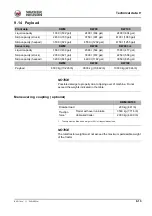
Page 203: ...multidisk brake on front and rear axles Location Front axle center housing Center housing of front and rear axles Effect Front wheels Direct Direct Rear wheels Via cardan shaft Parking brake DW60 DW90...

Page 204: ...22 4 6803 mm 22 4 Swivel skip 5998 mm 19 8 6546 mm 21 6 Operating hydraulics DW60 62 5 kW 83 8 hp DW60 DW90 DW100 55 kW 73 8 hp DW60 86 kW 115 3 hp DW90 DW100 Hydraulic pump 69 2 cm3 4 22 in3 78 1 cm3...

Page 205: ...16 mph 28 kph 17 mph 14 5 kph 9 mph Speed range 1 with Eco ON1 20 kph 12 mph 12 kph 7 5 mph Speed range 21 25 kph 16 mph with load 28 kph 17 mph without load 30 kph 19 mph 25 kph 16 mph Speed range 2...

Page 206: ...us 1 1 D18t900 fm 9 Technical data Fuse box Fuse box A is located at the front right of the chassis Main fuses B are located on the right Fig 210 A Fig 211 B Fig 212 Schematic fuse box assignment for...

Page 207: ...starter plus 12 V 15_1 fuse relay K1 F5 5A Fuel pump Engine control unit F6 15A Additional start quantity F7 15A F8 10A Horn1 F9 10A Horn1 rotating beacon1 F10 10A Brake lights1 F11 15A Starter F12 15...

Page 208: ...traffic regulations StVZO package option 2 Cabin or protective window option 3 The red camera display cable is fitted with an additional fuse DW 60 90 100 Working lights roof lights H3 12 V 55 W Inte...

Page 209: ...767 1480 1092 1770 1305 870 642 1250 922 M30 1420 1047 2010 1482 2400 1770 1200 885 1700 1254 Tightening torques fine pitch thread Property class 8 8 10 9 12 9 8 8 10 9 Screw dimen sions Screws accor...

Page 210: ...hp DW60 55 kW 73 8 hp DW60 86 kW 115 3 hp DW90 100 86 kW 115 3 hp Measured sound power level LwA 1 1 According to ISO 6395 EC Directives 2000 14 EC and 2005 88 EC 101 dB A 102 dB A 101 dB A 103 dB A G...

Page 211: ...itions use the average vibration values measured In order to obtain the estimated vibration value for an experienced operator on level ground subtract the factors from the average vibration value In c...

Page 212: ...the following activities smoothly without any jerks Steering Braking Acceleration Shifting gears Move attachments without any jerks Adapt your speed and the itinerary to minimize vibration Travel aro...

Page 213: ...ing machines This method is based on vibration measurements under real operating conditions for all machines Read the original guidelines This chapter summarizes part of the legal regulations However...

Page 214: ...perating weight 2 2 Operating weight machine full fuel tank skip operator 75 kg 165 lbs 4614 10 172 5314 11 715 5359 11 815 Front skip cabin DW60 kg lbs DW90 kg lbs DW100 kg lbs Transport weight1 4732...

Page 215: ...700 gal 3750 l 991 gal 4100 l 1083 gal Skip capacity heaped 3500 l 924 gal 4550 l 1202 gal 4750 l 1255 gal Swivel skip DW60 DW90 DW60 3 m Liquid capacity 1660 l 439 gal 2060 l 544 gal 1580 l 417 gal...

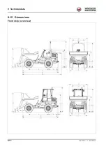
Page 216: ...9 16 BA D18 us 1 1 D18t900 fm 9 Technical data 9 15 Dimensions Front skip overview...

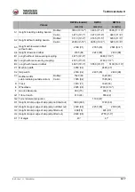
Page 217: ...aneuvering coupling 4575 15 0 4760 15 7 B3 Length with lowered rollbar 4945 16 3 5550 18 3 5130 16 10 C1 Machine width 2250 89 2465 97 C2 Skip width 2330 92 2495 98 2490 98 C3 Rollbar width cabin incl...

Page 218: ...9 18 BA D18 us 1 1 D18t900 fm 9 Technical data Swivel skip with rollbar overview...

Page 219: ...5085 16 8 B2 Length with maneuvering coupling 4935 16 2 4770 15 8 5185 17 0 B3 Length with lowered rollbar 5300 17 5 5135 16 10 5550 18 3 C1 Machine width 2250 86 2465 97 C2 Skip width 2090 82 2275 9...

Page 220: ...9 20 BA D18 us 1 1 D18t900 fm 9 Technical data Swivel skip with cabin overview...

Page 221: ...1920 76 E Wheelbase 2485 98 2700 8 10 F Ground clearance 369 15 406 16 G1 Tilt out reach 505 20 490 19 480 19 G2 Tail end lateral projection 1190 47 H1 Height of dump edge of skip skip not tilted out...

Page 222: ...9 22 BA D18 us 1 1 D18t900 fm 9 Technical data...

Page 223: ...ce 9 14 I Information before putting into operation 4 29 Information on this Operator s Manual 1 1 L Labels Information labels 3 12 Warning labels 3 8 Lateral angle of inclination 5 14 Letting the eng...

Page 224: ...rance ground pressure 9 14 Machine weights 9 14 Maximum speed 9 5 Noise emissions 9 10 Operating hydraulics 9 4 Swivel skip with cabin dimensions 9 20 Swivel skip with rollbar dimensions 9 18 Tighteni...

Page 225: ...at have already been delivered and that will not be implemented on these machines Technical data dimensions and weights are only given as an indication Responsibility for errors or omissions not accep...

Page 226: ......

Page 227: ......

Page 228: ...rveonderdelen Importante Para obter informa es sobre as pe as sobresselentes consulte o seu fornecedor da Wacker Neuson ou aceda ao site Web da Wacker Neuson em http www wackerneuson com Wa ne W celu...

Reviews: