151
22. NC rotary table (optional)
The NC rotary table is used to control the fourth axis in conjunction with nccad professional.
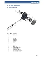
The housing body (1) has 4 flutes that enable the clamping of the NC rotary table in both the vertical
and the horizontal plane.
In order to be able to control the NC rotary table with the control software, this must first be
parameterised and activated in nccad professional as described in the enclosed parameter
sheet.
22.1 Clamping of work pieces on the NC rotary table
The work piece to be processed is clamped using T-nuts or hexagonal screws in the intended T-
shaped grooves of the rotary table.
When using lathe chucks, the chuck flange is clamped using T-nuts or hexagonal screws in the
intended T-shaped grooves of the rotary table (2). The work piece to be processed is, in turn, clamped
in the lathe chuck.
22.2 Swivelling the worm shaft in and out
The swivelling of the worm shaft in and out is not necessary in CNC mode. But if the worm shaft is
accidentally (e.g. by way of collision) swivelled out, then it must be brought back into contact with the
worm gear.
To set, proceed as follows:
1. Undo the locking screw (11) the eccentric tappet can now be rotated.
2. The eccentric tappet is easiest to set by swivelling the NC drive unit.
3. In order to bring the worm shaft into contact with the worm gear, the eccentric tappet must be
rotated anti-clockwise (swivel the NC drive unit backwards).
4. After successfully setting, tighten up the locking screw (11) again.
5. An incorrect setting of the NC drive unit may be corrected by undoing the screw (29) and then
swivelling the unit.
6. Then tighten the screw (29) again.
Summary of Contents for CC-F1200 high speed
Page 42: ...42 6 Fitting and removing the tools 1 2 3 4 5...
Page 68: ...68 17 Drawings and legends 17 2 Electronic hood with 1 4 kW motor 17 2 2 CC F1200 CC F1210...
Page 70: ...70 17 Drawings and legends 17 3 Milling head with 1 4 kW motor...
Page 72: ...72 40 1 51004008 0002 Mounting pin 17 Drawings and legends 17 4 Milling head with 2 0 kW motor...
Page 74: ...74 17 Drawings and legends 17 4 Milling head with 2 0 kW motor...
Page 76: ...76 17 Drawings and legends 17 5 Z stand with vertical skid with trapezoidal threaded spindle...
Page 82: ...82 17 7 Lateral drive for z axis with trapezoidal threaded spindle 17 Drawings and legends...
Page 84: ...84 17 8 Cross slide support with trapezoidal threaded spindle 17 Drawings and legends...
Page 94: ...94 17 Drawings and legends 17 11 Z stand with vertical skid with ball screw spindle...
Page 100: ...100 17 Drawings and legends 17 13 Lateral drive for z axis with ball screw spindle...
Page 102: ...102 17 Drawings and legends 17 14 Cross slide support with ball screw spindle...
Page 114: ...114 17 Drawings and legends 17 20 Operating console for 1 4 kW motor...
Page 116: ...116 17 Drawings and legends 17 20 Operating console for 1 4 kW motor...
Page 118: ...118 17 Drawings and legends 17 21 Operating console for 2 0 kW motor...
Page 120: ...120 17 Drawings and legends 17 21 Operating console for 2 0 kW motor...
Page 122: ...122 17 Drawings and legends 17 22 Bracket arm for operating console...
Page 124: ...124 17 Drawings and legends 17 23 Industrial monitor and folio keyboard...


