10
Components
Installation
4.1
Supply cable
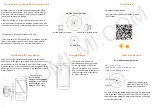
The supply cable has a connector at one end and three exposed cores at the other end. The
connector is used to connect the cable to the MCG via the X1 connecting socket on the device.
The three cores must be connected to the vehicle network, with respect to which the following must
be noted:
CORE
FUNCTION
Red core
Steady positive voltage
Black core
Vehicle mass
Green core
Ignition plus
4.2
Data cable
The data cable has three connectors. The 54-pole connector is used for the connection to the
MCG. The X3 socket is provided on the device for this purpose. After connecting the connector, the
connector lever must be flipped to arrest the connector correctly.
The 6-pole connector is used for the connection to the source CAN bus (vehicle bus). The 4-pole
connector is provided for the connection to the target device.
4.3
Connecting cable to the source CAN bus
The connecting cable contains two cores and is used as a connecting piece between the data cable
and the target CAN bus. The open line ends must be connected to the vehicle, the connector at the
other end is connected to the 6-pole connector of the data cable.


