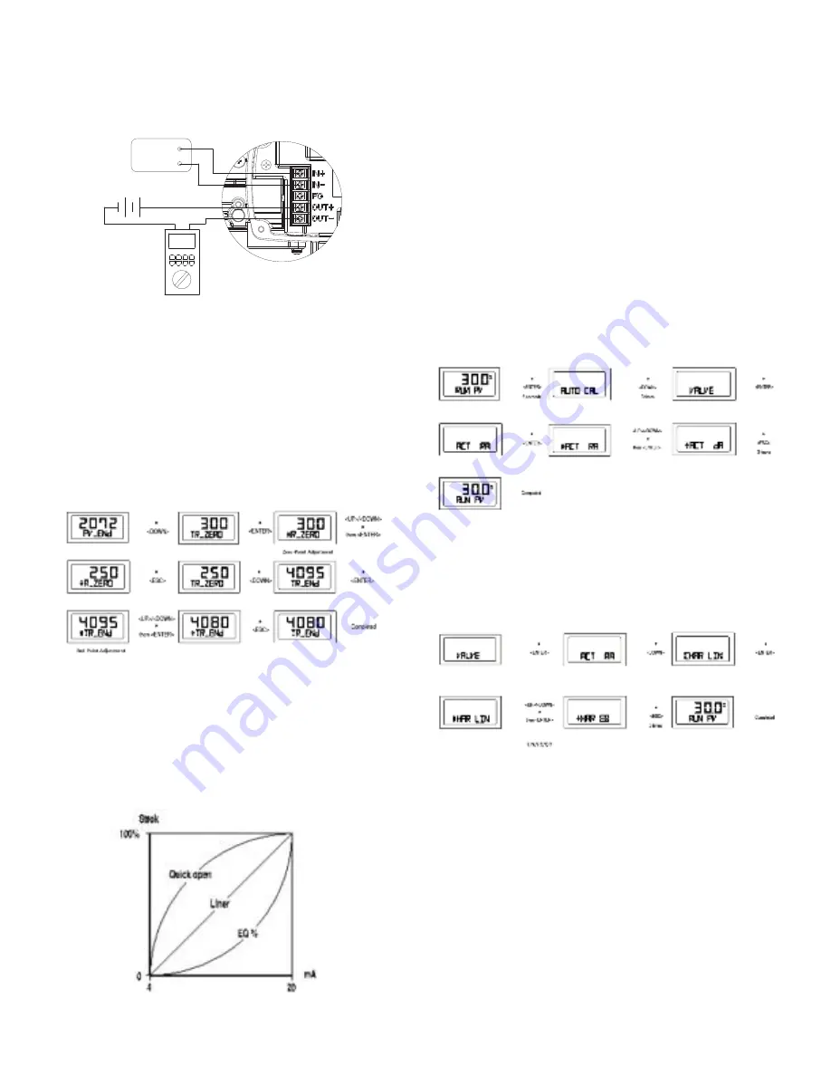
Adjustment of zero point (1 to 4) and end point (5 to 9) of transmitter.
If valve zero point and end point are changed, transmitter is also changed
automatically. Usually there is no need for the transmitter zero point and end
point to be adjusted by users, but if transmitter output signal is unstable,
transmitter zero point and end point should be adjusted. The ammeter showing
feedback signal is necessary and the connection should be down as shown.
1. Push <DOWN> at PV-END mode and then TR_ZERO mode is displayed.
2. Push <ENTER>. *R_ZERO mode is started and at this mode users can adjust
the zero point of the transmitter. Valve stem is moved to zero point automatically.
3. Push <UP> or <DOWN>. The number on the LCD is changed and the
measured current value is changed accordingly on an ammeter equipped outside.
Adjust it to be 4 mA and push <ENTER> to save it. +R_ZERO message is
displayed.
4. Push <ESC>. TR_ZERO mode is displayed.
5. Push <DOWN> at TR_ZERO mode. Then TR_END mode is displayed. (Push
<ESC> twice to return to RUN mode.)
6. Push <ENTER>. *TR_END mode is started and at this mode users can adjust
the end point of transmitter. Valve stem is moved to the end point automatically.
7. Adjust measured current value to be 20 mA on ammeter with <UP> or
<DOWN> buttons. Push <ENTER> to save it. +R_END message appears.
8. Push <ESC>. TR-END mode is displayed.
9. Push <ESC> twice to return to RUN mode.
Valve Mode
This mode adjusts the various characteristics.
Action Type (ACT)
It can be set to Direct Action (DA) or Reverse Action (RA).
Characteristics (CHAR)
Set Characteristics. There are three types of valve characteristics: Linear (LIN),
EQ% (EQ), and Quick Open (QO). The following is the example of the three
characteristic curves.
User Characteristics (USER SET)
When a specific characteristic is needed but not included in the above
characteristics, the user can make a specific characteristic curve by choosing 16
points voluntarily according to the field conditions the user’s need.
Tight Shut Open (TSHUT OP)
This allows the user to fully open valve at any value around the 20 mA current
input signal.
Tight Shut Close (TSHUT CL)
This allows the user to completely close valve at value around 4 mA input signal
from outside.
Split Range Control (SPLIT)
This allows the user to control entire stroke with input signals of 4 to 20 mA, 4 to
12 mA or 12 to 20 mA.
Adjustment of Acting Type (ACT)
1. Push <ENTER> at RUN mode for six seconds and then AUTO CAL mode is
displayed. Push <DOWN> four times to go into VALVE mode.
2. Push <ENTER> and ACT RA (in case of RA) is displayed.
3. Push <ENTER> again, then *ACT RA is displayed.
4. Adjust to *ACT DA by pushing <UP> or <DOWN> and save it with <ENTER>.
+ACT DA message appears.
5. Push <ESC> three times to return to RUN mode.
Adjustment of Characteristics (CHAR)
1. Push <ENTER> at VALVE mode and then push <DOWN>. CHAR LIN (in case
of linear characteristics) mode is displayed.
2. Push <ENTER>. *HAR LIN mode is displayed and characteristics can be
adjusted at the mode.
3. Adjust Characteristics (ex: EQ) by pushing <UP> or <DOWN> and save it with
<ENTER>. + HAR EQ is displayed.
4. Push <ESC> three times to return to RUN mode.
Adjustment of User Characteristics (USER SET)
1. Push <ENTER> at VALVE mode and ACT RA or ACT DA is displayed.
2. Push <DOWN> twice, then USER SET mode is started.
3. Push <ENTER>. *PO SET mode is displayed. In this mode, users can adjust
the first point of characteristic in 16 points. The number on the LCD is the valve
stroke percentage set to P0.
4. Adjust the valve stroke percentage using <UP> or <DOWN>.
5. Save it with <ENTER>. While P0 value is being saved, *P1 SET mode is
displayed.
6. *P1 SET mode is used to adjust the second point characteristic in 16 points.
Adjustment method is the same as P0* SET mode.
7. Save the valve stroke percentage from P2 to P15 SET mode; save it with
<ENTER>.
8. After adjustment of valve stroke percentage at *P15 SET mode, save it with
<ENTER>.
9. +SER SET is displayed. Sixteen points of valve stroke percentage are all set.
Push <ESC> three times to return to RUN mode.
Feed back signal
(12 ~ 30V)
4 ~ 20 mA
INPUT


