8
FUNCTIONAL DESCRIPTION
Your new air compressor can be used for operating paint, weed killer, and insecticide
sprayers, air tools, grease & caulking guns, sandblasters, inflation, etc. A tool with a higher air
demand than this compressor can produce may either not function, or not function well. It may
also cause the compressor to run without stopping for long periods of time, trying to maintain
pressure in the tank. This can cause either the motor or compressor pump to overheat and
damage them. Be sure the requirements of your tools can be met by the compressor.
To compress air, the piston in the pump moves up and down in the cylinder. On the down
stroke, air is drawn in through the inlet valve. Since the discharge valve remains closed, as the
piston goes up, the air in the cylinder is compressed. The inlet valve closes and compressed
air is forced out into the air receiver. A check valve prevents it from going back into the pump.
Working air is not immediately available. The pump continues to add air until the air receiver
pressure builds to above that required at the regulator.
SET-UP
After removing it from the carton, and before you can use your compressor, you must perform
some work preparatory to using your compressor:
You will need:
l
flat blade screwdriver
l
8 fl.oz. SAE-20 or SAE-10 non-detergent compressor oil
l
Pipe thread sealant tape
OIL
WARNING
!
This compressor requires oil of the correct type and quantity to run. Do not
start it without first following all the steps in this
section.
1. Be sure the compressor is on a level surface.
2. With the screwdriver, pry off and remove the shipping
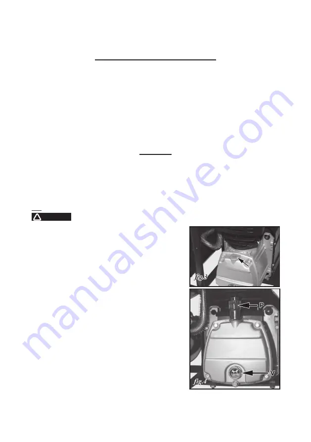
plug from the top of the crankcase (
fig.3
) revealing the
oil fill hole.
3. Through this hole, fill the oil reservoir with SAE-20
(API CG/CD heavy duty), non-detergent compressor
oil. In extreme winter conditions, use lighter SAE-10
weight.
4. The reservoir capacity is approximately 8 fl.oz. There
may be some oil left over from the manufacturing
process already in the reservoir. Be careful not to
overfill.
5. Check the oil level sight glass (
V in fig.2 & 4
). The oil
should show level with the red dot in the centre of the
viewing window.
6. Find the oil fill plug/breather cap (
P in fig.1, 2 & 4
). It is
usually shipped separately from the compressor and
enclosed with this manual. Be sure there is a rubber
O-ring on the threaded end.
7. Put a little pipe thread sealing tape on the threaded
end of the oil fill plug/breather cap.
Summary of Contents for 176-6799
Page 6: ...Nomenclature for No 176 6799 2 5 HP Air Compressor...
Page 18: ...18...
Page 19: ...19...
Page 20: ...20...
Page 21: ...21...
Page 22: ...22...
Page 23: ...23...
Page 24: ...24...
Page 25: ...25...
Page 26: ...26...
Page 27: ...27...
Page 28: ...28...
Page 29: ...29...
Page 30: ...30...
Page 31: ...31...
Page 32: ...32...
Page 38: ...38 Nomenclature pour no 176 6799 Compresseur air 2 5 HP...
Page 51: ...51 SCHEMATIC DRAWING SCH MA...


