


Information furnished by VubIQ is believed to be accurate and reliable. However, no responsibility is assumed by VubIQ for its use, nor for any infringements of patents or
other rights of third parties that may result from its use. Specifications subject to change without notice. No license is granted by implication or otherwise under any patent
or patent rights of VubIQ. Trademarks and registered trademarks are the property of their respective owners.
VuTxWGM3.7.02.13
VubIQ, Inc.
+1-949-226-7185 [email protected]
9231 Irvine Blvd, Irvine, California 92618 USA www.vubiq.com
7
4.0 GUI Control Software
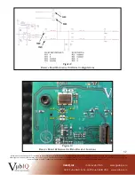
As shown in Figure 3, the transmitter and receiver boards are set up and controlled from a host PC running the
GUI software. The software can be downloaded from our web site
(
http://www.vubiq.com/customerdownloads.php
) as a ZIP file. Unzip the files and place into a convenient
directory on the PC that will be used with the development system test setup. With a transmitter and receiver
board connected via the USB cables to the PC, run the software (VubiqGUI.exe). A transmitter window and a
receiver window will appear showing the block diagrams. The transmitter board LED will illuminate red, and the
receiver LED will illuminate blue.
Each GUI window provides the user with the ability to set up various control parameters for the transmitter
and receiver boards. Board voltages and temperatures are also monitored. The window images are shown on the
following pages, Figures 4 and 5.
Figure 3
Various Test and Development Scenarios


