2
2) Digital I/O Box Connections
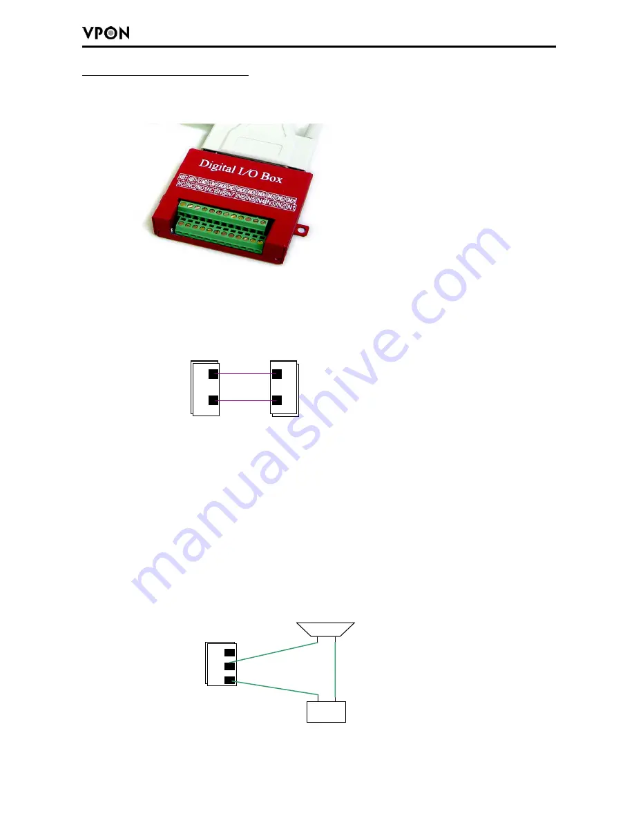
The digital I/O box is used to connect to alarm input and relay output.
I/O box(8 sensor input
、
2 relay output)
External alarm input:
The I/O box allows 8 digital inputs for sensors, divided in 8 groups:
(IN1 GND1), (IN2, GND2), …, (IN8, GND8).
Remark
: For each group,
IN
and
GND
can be configured as Normal Open (NO) or Normal
Close (NC) in the software.
Relay output
: The I/O box allows 2 digital relay outputs for alarm device (e.g. buzzer),
divided in 2 groups: (NC1, NO1, COM1) and (NC2, NO2, COM2)
The figure below gives an example for connecting a Buzzer to the I/O box. “DC power” is
an external power supply to the Buzzer. If the Buzzer is a NO device, you should connect it
to “NO 1” pin and leave the “NC 1” pin unconnected. If the Buzzer is a NC device, connect
it to “NC 1” pin and leave the “NO 1” pin unconnected.
IN 1
GND 1
I/O Box
Sensor
NC 1
NO 1
I/O Box
COM 1
DC power
+
-
+
-
Buzzer


