Voyager DP-263-S Installation And Operation Manual Download Page 15


14 

Under the Manager Menu option, press 

CALL button. 

Select Door Setting and press 

CALL button. 

Select Open by Password and press 

CALL button. 

Press CALL button to toggle between “Enabled” and “Disabled”.   

Press F1 (EXIT) button to return to the previous option screen and the last 

setting will be saved. 


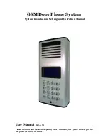
Change Door Opening Password 
Manager Setting 

 Door Setting 

 Opening Password 


Note: This GSM Door Phone system will allow the user to open door by pressing 6-digit 

password.    This feature is designed for easy access control. We suggest to change the   

Door Opening Password every month or every two weeks for security concern. 


Under the Manager Menu option, press 

CALL button. 

Select Door Setting and press 

CALL button. 

Select Opening Password and press 

CALL button. 

Enter password (must be 6 digits).   

Press 

CALL button to save the new password. 

Press F1 (EXIT) button to return to previous option screen. 
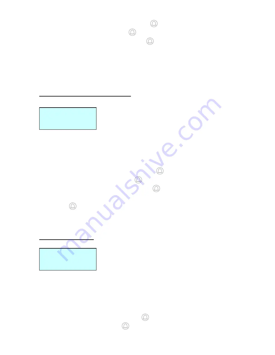
 
 
Door Opening Time 
Manager Setting 

 Door Setting 

 Door Open Time 


Note: This GSM Door Phone system will allow the user to set how long the door 
lock will be opened.    Sometimes, the user might need more time to reach from the 
door phone unit to the locked main gate.    We suggest to set enough time to allow 
him/her walk in no hurry.   


Under the Manager Menu option, press 

CALL button. 

Select Door Setting and press 

CALL button. 

Door Open Time     
 
03 Second(s) 

Opening Password 
 
Password: 123456 

Summary of Contents for DP-263-S

Page 1: ...oor Phone System System Installation Setting and Operation Manual User Manual 263 S V1 Please read this user manual completely before operating this system and keep it in a safe place for future refer...

Page 2: ...tes for Talk Time VOLUME SETTING Change Microphone Volume Change Speaker Volume Change Speaker Volume During Conversation DOOR SETTING Enable Disable Door Lock Open by Password Change Door Opening Pas...

Page 3: ...epped on or where someone can trip over them 5 Do not use this product near an area where there is a potential of gas leaks or near any fumes that can be explosive 6 Do not place this equipment near o...

Page 4: ...stem will include the followings 1 x Door phone unit 1 x AC power adapter 1 x GSM antenna 1 x Wall mounting bracket 1 x Wire 4 x screws for mounting bracket 2 x screws for door phone 1 x User manual O...

Page 5: ...m Diagram Front View Acrylic cover Speaker LCD display Keypad 0 9 Number keys F1 Menu Exit key F2 Delete key F3 ABC abc 123 exchange button Volume select up key Volume select down key Microphone Botto...

Page 6: ...m Diagram Back View Opening for connecting wall mount bracket Metal back cover plate Opening for connecting wall mount latch SIM card slot Wiring terminal USB port GSM antenna Bottom cover GSM Antenna...

Page 7: ...6 System Diagram Wall Mounting Bracket...

Page 8: ...wires through the hole Then refer to the Wiring Diagram and Wiring Instruction to connect wires and insert the SIM card to SIM card slot as Step 3 shown below 3 Put the bottom cover back as Step 4 sho...

Page 9: ...AC adapter into the AC outlet then the door unit will go into standby mode WARNING Only use the original power adapter supplied Using any other adapter might damage the door unit and cause a risk of e...

Page 10: ...your strike has one is connected to Terminal Pin 6 The system will supply 12 volts DC at 1000mA 3 Install Door Lock with its own Power Supply Wiring If the door lock comes with its own power supply o...

Page 11: ...few seconds and then go to standby mode Turn the power off Turn off the door unit by unplugging the power adapter from the AC power outlet Manager Mode and Functions Note The unit will be time out af...

Page 12: ...bers and settings Under the Manager Menu option press CALL button Select System Setting and press CALL button Select Change Password and press CALL button Enter new password by Number button must be 6...

Page 13: ...d press CALL button Input the number for minutes you will need for the intercom to be made without re dial then press CALL button to save Press F1 EXIT button to return to previous option screen Volum...

Page 14: ...o adjust volume Press F1 EXIT button to return to the previous option screen and the last setting will be saved automatically Change Speaker Volume during Conversation At any time during the conversat...

Page 15: ...ery two weeks for security concern Under the Manager Menu option press CALL button Select Door Setting and press CALL button Select Opening Password and press CALL button Enter password must be 6 digi...

Page 16: ...s Number button to set calling time Press F1 EXIT button to return to the previous option screen and the last setting will be saved Change the Calling by List Manager Setting Calling Setting Calling b...

Page 17: ...er Setting Enter Subscriber ID _ Select Subscriber Menu option and press CALL button You can choose from 1 digit to 6 digits for the Subscriber ID Enter Subscriber ID _____ and press CALL button Press...

Page 18: ...dial tone and go back to standby mode If the call is not answered within one minute the screen will show No answer and go back to standby mode During conversation if the other party hangs up or the li...

Page 19: ...en the system is turned on Call Manager If Manager Phone has been programmed the system will directly dial this number while the visitor presses CALL button at the standby mode If Manager Phone is not...

Reviews: