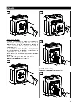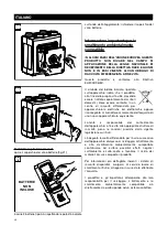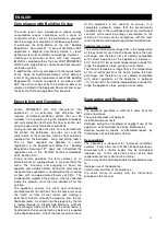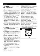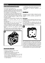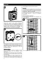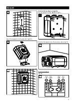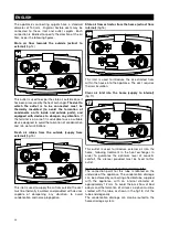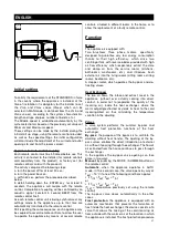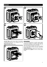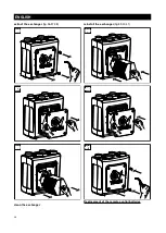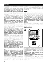
SUMMER (fig.27c):
this forces the opening of the by-pass valve, irrespective
of the actual desired internal, desired or external
temperature values.
The shift from one operating mode to the other is
achieved by pressing the MODE button for at least 0.5
seconds.
NEXT, - +, ENTER buttons
(fig.28)
Already described in other parts of this document.
Disabling certain commands
(by the Installer)
To satisfy the requirements of some specific application
certain functions accessible through the remote control
may be disabled by the installer. In this case the
appliance will operate in AUTO mode only: the user
can only set the TIMER function and change the time or
day of the week using the SET button to set the TIMER
and display:
the actual temperature
of the stail air, before the heat
exchanger;
the relative humidity percentage
of the stail air, before
the heat exchanger;
the CO2 concentration
of the stail air, before the heat
exchanger;
the TIMER setting
.
Pressing the other buttons, will be considered an
accidental event and will cause any action.
Prevention of changes to Vmin and Vmax speed
The installer can prevent others from making changes to
the maximum and minimum speed settings once he has
made the initial settings.
Warning/error signals
• Exceeding the CO2 threshold generates an alarm
condition, which results in the flashing of the CO2
value on the remote control display. The appliance
starts running at Max speed until CO2 level has
dropped.
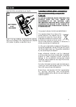
• Low battery is indicated on the remote control by a
flashing of the relative icon
and an acoustic signal
(a sequence of double BEEPs).
Once the expired
batteries have been replaced, the acoustic warning
will stop and the icon will go off.
• The dirty filter condition is indicated by an acoustic
signal (a sequence of triple BEEP’s) and the flashing of
the relative icon
. This signal is interrupted when
the filter maintenance or cleaning procedure is being
carried out.
• The saturated filter condition is indicated with an
acoustic signal (a continuous sound) and the
permanent display of the relative icon
. In this
event, the appliance automatically stops the motors
and opens the by-pass valve to ensure that there is
however at least some air circulation. This signal is
interrupted when the filter maintenance or cleaning
procedure is being carried out.
Error warnings are indicated
on the display by the
relative codes (ER01, ER02, etc…) and
an acoustic
warning signal (a sequence of double BEEPs). These
warnings will remain in effect until the regular operating
conditions of the appliance have been restored, or the
appliance has been turned off. The malfunctions will be
indicated as:
ER01
: by-pass / de-frosting valve blocked;
ER02
: blockage of the fan motor intaking fresh air from
outside;
ER03
: blockage of the motor discharging the stale air to
outside;
ER04
: the remote control does not receive signals from
the appliance
ER05
: the remote control is not transmitting signals to
the appliance.
ER06
: the temperature sensor in the external fresh air
intake duct upsteam of the exchanger is not active;
ER07
: the temperature sensor in the external fresh air
intake duct downsteam of the exchanger is not active;
ER08
: the temperature sensor in the stale air outlet
delivery duct from the house downstream of the
exchanger is not active;
ER09
: the Relative Humidity sensor in the stale air
outlet delivery duct from the house upstream of the
exchanger is not active;
ER10
: the CO2 sensor in the stale air outlet delivery
duct from the house upstream of the exchanger is not
active;
ER11
: the outside temperature is lower than the limit
value;
ER12
: the outside temperature is higher than the limit
value;
28
28
SET
NEXT
ENTER
DISPLAY
TIMER MODE
14:38
AUTO
Fr
27c
27c
14:38
SUMMER
Fr
MAN
33
ENGLISH

