background image

Frame and Equipment Supplied

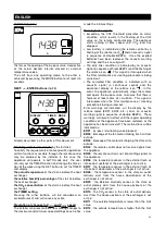
The main parts of the appliance are:
• the casing, comprised of two parts, which integrate
the spigots provided for connection with the air inlet and
outlet ducts and contains the internal components and
heat exchanger in an air tight housing;
• the internal air ways, that distribute the air flow
maximizing the heat insulation and minimizing losses;
• the heat exchanger, made out of plastic resin and of
counter flow type, whose particular shape guarantees
the highest possible efficiency in terms of heat
exchange up to 95%;
• the two motors, of the brushless three phase variety,
mounted on anti-vibration supports, that drive the
impellers;
• the stepping motor, that controls the by-pass and
defrosting valves;
• the electronic control suite, that oversees the power
supply, the appliance commands and controls;
• the sensors (temperature, relative humidity and CO2),

on the basis of which the systems electronic controls
establishes automatically the appliance’s operating
mode.
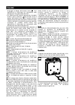
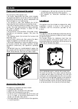
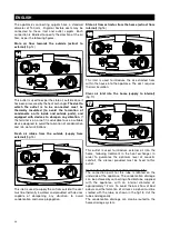
• ATTENTION: to be truly “UK APPENDIX Q” eligible, the
cap supplied with the appliance should be inserted into
the de-frost protection valve inlet, as shown in fig.2.

Accessories Supplied

The appliance supplied accessories include:
• a condensation drain pipe;
• a pipette for the connection of the drain pipe;
• 2 filters with F5 level particle retention;
• A silencer, with a standard diameter of 150 mm and

0.5 m in length, to be placed downstream of the
product, on the room intake ducts;

• two metal brackets, on which to mount the apparatus

in a vertical position;

• a radiofrequency (RF) remote control for the initial set

up and subsequent operation of the appliance;

• four supports for horizontal installation of the

appliance.

Installation

The appliance must be installed according to the safety
regulations currently in force in the country of
installation, and the instructions provided by this
manual.

Prerequisites

The appliance must be installed on an internal surface or
wall of the home structurally suitable to hold it’s weight
(at least 200 Kg/m

2

)

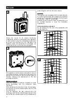
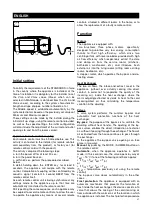
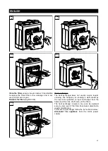
The location chosen for installation must take into
account the position of the power supply cable, 1.5 m
long and the electrical connections, that come out of the
under side of the apparatus (fig.3).

The air distribution ducts must be of the correct size.
The ducts to and from the exterior must be thermally
insulated and not subject to vibrations. The inlet and
outlet ducts, of a standard diameter of 150 mm, must be
secured to the corresponding spigots of the appliance
by means of clips or other suitable fastening systems.
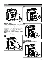
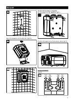
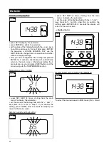
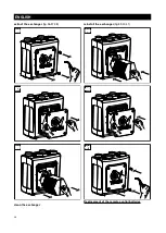
In order to optimize acoustic levels the silencer provided
must be mounted on the air feed into the home (fig.4).

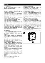
3

 3

2

 2

23

ENGLISH

Summary of Contents for VORT PROMETEO HR 400

Page 1: ...IMITED Beeches House Eastern Avenue Burton on Trent DE13 0BB Tel 44 1283 492949 Fax 44 1283 544121 UNITED KINGDOM VORTICE FRANCE 72 Rue Baratte Cholet 94106 Saint Maur Cedex Tel 33 1 55 12 50 00 Fax 33 1 55 12 50 01 FRANCE VORTICE ELETTROSOCIALI S p A Strada Cerca 2 frazione di Zoate 20067 TRIBIANO MI Tel 39 02 90 69 91 Fax 39 02 90 64 625 ITALIA COD 5 371 084 606 14 07 2009 ...

Page 2: ...ren sind Befolgen Sie alle Anweisungen um eine lange Lebensdauer sowie die elektrische und mechanische Zuverlässigkeit des Gerätes zu gewährleisten Diese Betriebsanleitung ist gut aufzubewahren Indice IT Conformità con i regolamenti edilizi 4 Descrizione ed impiego 4 Garanzia e responsabilità 4 Attenzione 5 Avvertenza 5 Struttura e dotazione 6 Accessori in dotazione 6 Installazione 6 Configurazion...

Page 3: ...odobou životnost výrobku a jeho elektrickou i mechanickou spolehlivost Tento návod k použití si proto uschovejte Inhoudsopgave NL Conformiteit met Bouwreglementen 73 Beschrijving en gebruik 73 Garantie en aansprakelijkheid 73 Let op 74 Waarschuwing 74 Structuur en toebehoren 75 Bijgeleverde accessoires 75 Installatie 75 Voor het eerst instellen 79 Werking 79 Gebruiksaanwijzing 81 Zekering 86 Onder...

Page 4: ...accoglie all interno del prodotto deve essere poi convogliata all esterno L apparecchio garantisce una silenziosa e continua ventilazione estrazione dell aria dalla casa rimuovendo l aria viziata da tutte le stanza umide e creando un percorso d aria permanente attraverso l apparecchio dai locali abitativi secchi L aria convogliata nell apparecchio viene immessa in uno scambiatore di calore ad alta...

Page 5: ...r l eventuale riparazione l uso di ricambi originali Vortice Se il prodotto cade o riceve forti colpi farlo verificare subito presso un Centro di Assistenza Tecnica autorizzato Vortice L installazione dell apparecchio deve essere effettuato da parte di personale professionalmente qualificato L apparecchio deve essere montato in modo da garantire che in condizioni normali di funzionamento nessuno p...

Page 6: ...ne verticale dell apparecchio un telecomando a radiofrequenza RF per l impostazione iniziale ed il successivo controllo dell apparecchio quattro supporti per installazione in orizzontale del apparecchio Installazione L apparecchio deve essere installato seguendo le norme di sicurezza in vigore nel paese di destinazione e le istruzioni del presente libretto Prerequisiti L apparecchio deve essere in...

Page 7: ...re che il nome e la descrizione riportati sulla scatola siano corretti estratto l apparecchio dall imballo verificare che non siano presenti danni visibili quindi accertarsi della presenza del tubetto per lo scarico della condensa e del libretto istruzioni Montaggio L apparecchio è equipaggiato con due staffe metalliche per il montaggio verticale a parete e di 4 supporti per il posizionamento orizz...

Page 8: ... apparecchio hanno diametro interno nominale pari a 150 mm Alle bocche dell apparecchio possono essere collegati tubi rigidi o flessibili Nel seguito ogni connessione è illustrata da una figura che specifica anche le direzioni di provenienza e mandata del flusso d aria 12 12 MANDATA ARIA VIZIATA VERSO L ESTERNO ASPIRAZIONE ARIA FRESCA DALL ESTERNO ASPIRAZIONE ARIA VIZIATA DA CASA MANDATA ARIA PULITA I...

Page 9: ...di rumori Aspirazione aria viziata da casa extract from internal fig 15 Questa bocca è utilizzata per convogliare nell apparecchio l aria estratta dall interno della casa Il condotto richiede isolamento termico Mandata aria pulita in casa supply to internal fig 16 Questa bocca è utilizzata per immettere all interno della casa l aria esterna opportunamente trattata nello scambiatore di calore Per gar...

Page 10: ...ntire all utente il controllo dell apparecchio mediante più telecomandi situati in locali diversi dell abitazione ovvero per permettere la sostituzione di un telecomando guasto Funzionamento Motori L apparecchio è equipaggiato di due motori brushless trifase specificamente studiati per garantire bassissimi consumi grazie alla loro elevata efficienza azionanti due ventole centrifughe a pale rovesce e...

Page 11: ...tigelo perché ciò potrebbe ostacolarne il regolare funzionamento Filtri Due filtri F5 alloggiati all interno dei canali di mandata ed estrazione in prossimità dello scambiatore di calore ed accessibili rimuovendo il pannello frontale lo salvaguardano dalle impurità contenute nell aria viziata espulsa e prevengono l immissione di aria inquinata nei locali asserviti Un ulteriore filtro opzionale di cl...

Page 12: ...ionale comprensivo di cavo di collegamento e disponibile come optional consente il controllo dell apparecchio anche nel caso in cui la posizione prescelta per la sua installazione risulti schermata alle onde radio fig 19 Modalità di Impiego Modalità di utilizzo del telecomando inserire le batterie fig 20 N B Dopo un certo periodo di inattività il telecomando entra in modalità pausa e per riattivarlo...

Page 13: ...econdi il tasto NEXT è possibile passare all impostazione del parametro temperatura Parametro temperatura fig 22b visualizzare il parametro tramite la pressione dei tasti SET NEXT 3 volte iniziando dal menu principale impostare il valore del campo lampeggiante tramite pressioni sui tasti e da 15 C a 30 C step 1 C per confermare premere il tasto ENTER dopo 4 secondi il display tornerà alla schermata...

Page 14: ...nza tramite pressioni ripetute di almeno 0 5 sec i seguenti parametri del sistema temperatura effettiva fig 24a durante il funzionamento normale rilevata dal sensore di temperatura posto nel canale di mandata da casa prima dello scambiatore di calore valore attuale dell umidità relativa fig 24b non impostabile dall utente rilevato dal sensore di temperatura posto nel canale di mandata da casa prima ...

Page 15: ...max per 10 min una pressione di 0 5 sec del tasto 20 min due pressioni del tasto 30 min tre pressioni del tasto o indefinitamente quattro pressioni del tasto Ad un ulteriore quinta pressione OFF del tasto l apparecchio torna a funzionare alla velocità in precedenza impostata fatti salvi i dettami dei sensori Contemporaneamente il display visualizzerà fig 25a l icona del TIMER la modalità di funziona...

Page 16: ...postare il TIMER e visualizzare la temperatura effettiva dell aria viziata prima dello scambiatore di calore la percentuale di umidità relativa dell aria viziata prima dello scambiatore di calore la concentrazione di CO2 nell aria viziata prima dello scambiatore di calore l avvenuta impostazione del TIMER La pressione di altri tasti verrà intepretata quale evento accidentale e non darà luogo ad az...

Page 17: ...temperatura esterna è superiore al valore limite ER13 la temperatura interna è inferiore al valore limite ER14 la temperatura interna è superiore al valore limite In particolare segnalazioni di errore codici ER01 ER02 ed ER03 riconducibili a malfunzionamenti critici del apparecchio daranno origine al suo arresto fino all avvenuta soluzione dei problemi relativi In tale situazione il segnale acustic...

Page 18: ... dei filtri una volta all anno Per accedere ai filtri rispettare le istruzioni seguenti spegnere l apparecchio tasto ON OFF attendere 15 secondi disconnettere l apparecchio dalla rete elettrica estrarre i filtri dall apparecchio fig 29 30 31 pulire i filtri utilizzando un aspirapolvere è preferibile sostituire i filtri dopo alcune puliture e comunque almeno 1 volta all anno rimontare i filtri fig 32 33...

Page 19: ... stato di efficienza dei filtri Lo scambiatore di calore dovrebbe comunque essere sostituito ogni 6 anni anche se è stata effettuata con regolarità la manutenzione dei filtri Per accedere allo scambiatore rispettare le istruzioni seguenti disconnettere l apparecchio dalla rete elettrica estrarre lo scambiatore fig 35 36 37 pulire lo scambiatore rimontare lo scambiatore fig 38 39 40 38 38 37 37 36 36 34...

Page 20: ...d elettroniche oppure riconsegnato al rivenditore al momento dell acquisto di una nuova apparecchiatura equivalente L utente è responsabile del conferimento dell apparecchio a fine vita alle appropriate strutture di raccolta pena le sanzioni previste dalla vigente legislazione sui rifiuti L adeguata raccolta differenziata per l avvio successivo dell apparecchio dismesso al riciclaggio al trattamen...

Page 21: ...t then be drained off to the outside The appliance ensures the silent and continuous ventilation extraction of the air from the home removing the stale air from all wet rooms and creating a permanent air path through the property from the dry habitable rooms Air drawn into the property by the fan is routed through an integral high efficiency synthetic heat exchanger where warmth from the extracted ...

Page 22: ...a heavy blow have it checked by Vortice immediately The appliance must be installed by a professionally qualified installer The appliance must be installed in such a way as to guarantee that in normal operating conditions no one can get close to any moving parts or live wires or other elements When dismantling the apparatus with suitable tools extracting the heat exchanger extracting the motor mod...

Page 23: ...a pipette for the connection of the drain pipe 2 filters with F5 level particle retention A silencer with a standard diameter of 150 mm and 0 5 m in length to be placed downstream of the product on the room intake ducts two metal brackets on which to mount the apparatus in a vertical position a radiofrequency RF remote control for the initial set up and subsequent operation of the appliance four su...

Page 24: ...ding with the installation More specifically firstly proceed with extracting it from the packaging ensuring that the name and description shown on the box correspond once the appliance has been removed from the packaging verify that no visible damage is present then ensure that the small drain pipe for the condensation is present together with the instruction manual Assembly The appliance comes equi...

Page 25: ...ssembly on supports Fix the supports to the appliance fig 11 Position the appliance on the location surface fig 12 Duct connections fig 13 13 13 EXTRACT TO EXTERNAL SUPPLY FROM EXSTERNAL EXTRACT FROM INTERNAL SUPPLY TO INTERNAL 12 12 11 10 10 9 9 8 8 25 ENGLISH ...

Page 26: ...ovided with devices capable of dampening any vibration to avoid condensation and noise propagation Stale air flow extractor from the home extract from internal fig 16 This inlet is used to introduce the air extracted from within the house into the appliance The duct requires thermal insulation Clear air inlet into the home supply to internal fig 17 This outlet is used to introduce external air into ...

Page 27: ...e is equipped with Two brushless three phase motors specifically designed to guarantee very low energy consumption thanks to their high efficiency which drive two centrifugal fans with reverse blades provided with high air flow efficiency which respectively extract the stale and damp air from the service rooms kitchens bathrooms washrooms etc and introduce fresh external air into the living rooms sitt...

Page 28: ...lter can provide an additional filtering capability The state of filter clogging is constantly monitored by the system completely automatically The need for maintenance replacement is signalled both visually and acoustically on the remote control Sensors The appliance is equipped with three temperature sensors one relative humidity sensor which integrates a further temperature sensor and a CO2 senso...

Page 29: ...use mode To reactivate it press and hold down one of the buttons ON OFF button fig 22 Enables the appliance to be turned on and off The command is performed only if the button is pressed for at least 0 5 seconds With the appliance off the time and day of the week are displayed This function may be disabled On turning the appliance on the AUTO mode is activated at a speed of Vmin SET button fig 23 Se...

Page 30: ...etting fig 23b press SET NEXT 3 times starting from the main menu to display the parameter set the value of the flashing field with the and keys from 15 C to 30 C step 1 C to confirm the setting press ENTER after 4 seconds the display will return to the main screen Relative humidity setting fig 23c press SET NEXT 4 times starting from the main menu to display the parameter set the value of the flashing ...

Page 31: ...heat exchanger Current humidity display fig 25b not settable by the user detected by the humidity sensor placed in the home air inlet shaft before the heat exchanger CO2 percentage display fig 25c not settable by the user detected by the CO2 sensor placed in the home air inlet shaft before the heat exchanger Residual operating time at Vmax fig 25d depending on preset Timer duration see TIMER button O...

Page 32: ... button 5 times until OFF appears the appliance will go back to working at minimum speed except commands from the RH and CO2 sensors and the display will no longer show the clock symbol MODE button fig 27 Allows the available operating modes MAN SUMMER AUTO to be selected AUTO fig 27a the operating speed is automatically set by the system depending on the environmental conditions detected by the sen...

Page 33: ...ple BEEP s and the flashing of the relative icon This signal is interrupted when the filter maintenance or cleaning procedure is being carried out The saturated filter condition is indicated with an acoustic signal a continuous sound and the permanent display of the relative icon In this event the appliance automatically stops the motors and opens the by pass valve to ensure that there is however at ...

Page 34: ...lem has been resolved Reset To reset equipment status if the remote control disabling procedure has not been carried out press the following keys in sequence DISPLAY Minus DISPLAY Plus After the RESET the appliance resumes operation in AUTO mode as per the initial standard parameters Any error messages is no longer displayed of course if the problem causing the malfunction has been solved Likewise...

Page 35: ...egular cleaning The frequency of cleaning is determined by the level of air pollution in input and output from the home and the state of efficiency of the filters The heat exchanger should in any case be replaced every 6 years even if the filters have been subjected to regular maintenance To access the exchanger follow the instructions below disconnect the appliance from the mains power supply 35 35 ...

Page 36: ...extract the exchanger fig 36 37 38 clean the exchanger reinstall the exchanger fig 39 40 41 Replacement of the remote control batteries 41 41 40 40 38 38 37 37 36 36 39 39 36 ENGLISH ...

Page 37: ...for waste electrical and electronic equipment or returned to a retailer on purchase of a replacement It is the user s responsibility to dispose of this appliance through the appropriate channels at the end of its useful life Failure to do so may incur the penalties established by laws governing waste disposal Proper differential collection and the subsequent recycling processing and environmentall...

Page 38: ...ion by subtracting for multi storey dwellings 0 04 x gross internal volume of dwelling heated space m 3 for single storey dwellings 0 06 x gross internal volume of dwelling heated space m 3 2 Calculate the whole dwelling extract rate at maximum operation by adding the individual room rates for minimum high rate from Table 1 1A 3 The required air flow rates as as follows Maximum Extract Rate boost ...

Page 39: ...reccueillie à l intérieur de l appareil doit être ensuite convoyée à l extérieur L appareil garantit une ventilation extraction continue et silencieuse de l air des pièces ou locaux L air vicié est extrait de toutes les pièces humides en créant un parcours d air permanent à travers l appareil vers les locaux ou pièces d habitation secs L air convoyé dans l appareil est introduit dans un échangeur ...

Page 40: ...s vente agréé Vortice et demander pour toute réparation des pièces détachées d origine Vortice Si l appareil tombe ou reçoit des coups violents le faire vérifier immédiatement auprès d un Service après vente agréé Vortice L installation de l appareil doit être faite par du personnel professionnellement qualifié L appareil doit être monté de sorte que en conditions normales personne n entre en cont...

Page 41: ...es de refoulement des pièces deux étriers en métal pour le montage mural de l appareil une télécommande à radiofréquence RF pour la programmation initiale et le contrôle ultérieur de l appareil quatre supports pour l installation de l appareil à l horizontale Installation L appareil doit être installé dans le respect des normes de sécurité en vigueur dans le pays de destination et des instructions...

Page 42: ...plus de précisions avant de procéder à son extraction de l emballage vérifier que le nom et la description mentionnés sur le carton sont corrects une fois l appareil extrait de son emballage vérifier qu aucun dommage ne soit apparent S assurer ainsi de la présence du tube d évacuation de la condensation et de la notice d instructions Montage L appareil est équipé de deux étriers en métal pour le mon...

Page 43: ... nominal interne de près de 150 mm Des tuyaux rigides ou flexibles peuvent être reliés aux bouches de l appareil Dans les sections qui suivent chaque raccordement est illustré par une figure qui précise également les directions de provenance et le refoulement du flux d air 12 12 REFOULEMENT AIR IMPUR VERS L EXTERIEUR ASPIRATION AIR FRAIS DE L EXTERIEUR ASPIRATION AIR IMPUR DE LA MAISON REFOULEMENT AI...

Page 44: ...pagation de bruits Aspiration de l air impur de la maison extract from internal fig 15 Cette bouche est utilisée pour convoyer dans l appareil de l air extrait de l intérieur de la maison Le conduit exige isolation thermique Refoulement d air pur dans la maison supply to internal fig 16 Cette bouche est utilisée pour introduire dans la maison de l air provenant de l extérieur Cet air a été traité c...

Page 45: ...itation ainsi l utilisateur pourra toujours contrôler l appareil ou bien remplacer une télécommande endommagée Functionnement Moteurs L appareil est équipé de Deux moteurs sans balais triphasés spécialement conçus pour garantir une faible consommation d énergie grâce à leur grande efficicacité actionnant deux hélices centrifuges à pales inversées et à haute efficacité aéraulique qui extraient respec...

Page 46: ...ar le système garantit l atteinte de l objectif IMPORTANT veillez à ce qu aucun objet ne soit placé en face de la soupape de protection antigel il pourrait entraver la régularité de son fonctionnement Filtres Deux filtres F5 logés à l intérieur des conduites de refoulement et d extraction situées à proximité de l échangeur de chaleur et accessibles en ôtant le panneau frontal le protégent des impur...

Page 47: ...l dysfonctionnement de l appareil Dispositif RF additionnel Fourni en option un dispositif émetteur récepteur radiofréquence additionnel comprenant un câble de raccordement permet de contrôler l appareil notamment dans le cas où l emplacement préalablement choisi pour son installation ferait écran aux ondes radio fig 19 Mode d emploi Mode d emploi du télécommande Mettre en place les piles fig 20 N ...

Page 48: ...SUIVANT sans attendre 4 sec pour définir le paramètre TEMPÉRATURE Paramètre température fig 22b visualiser le paramètre en appuyant sur les touches SET NEXT 3 fois en commençant par le menu principal introduire la valeur du champ clignotant en appuyant sur les touches e de 15 C à 30 C step 1 C pour confirmer appuyer sur la touche ENTRÉE Au bout de 4 sec l écran revient à la page principale Paramètr...

Page 49: ...0 5 seconde environ les paramètres suivants du système La température effective fig 24a celle relevée par le capteur de température placé dans la conduite de refoulement de la maison avant l échangeur de chaleur La valeur actuelle de l humidité relative fig 24b celle relevée par le capteur de température placé dans la conduite de refoulement de la maison avant l échangeur de chaleur non programmable...

Page 50: ...cer l appareil à fonctionner à Vmax pendant 10 min une pression de 0 5 sec de la touche 20 min deux pressions de la touche 30 min trois pressions de la touche ou à l infini quatre pressions de la touche Une cinquième pression OFF de la touche permet à l appareil de fonctionner à nouveau à la vitesse précédemment programmée sauf les réglages des capteurs Le panneau d affichage indique au même moment ...

Page 51: ... heure jour de la semaine avec la touche RÉGLAGE programmer le TEMPORISATEUR et visualiser la température effective de l air vicié avant l échangeur de chaleur le pourcentage d Humidité Relative de l air vicié avant l échangeur de chaleur la concentration de CO2 de l air vicié avant l échangeur de chaleur le réglage de la minuterie TIMER La pression d autres touches en plus des trois décrites ci d...

Page 52: ...a maison en amont de l échangeur n a pas été activé ER11 la température extérieure est inférieure à la valeur limite ER12 la température extérieure est supérieure à la valeur limite ER13 la température intérieure est inférieure à la valeur limite ER14 la température intérieure est supérieure à la valeur limite Les signaux d erreur codes ER01 ER02 et ER03 qui correspondent à un disfonctionnement gr...

Page 53: ...s une fois par an Afin d accéder aux filtres veuillez respecter les instructions suivantes couper l alimentation de l appareil touche ON OFF attendre 15 secondes débrancher l appareil du réseau électrique extraire les filtres de l appareil fig 29 30 31 nettoyer les filtres à l aide d un aspirateur il est préférable de remplacer les filtres après plusieurs nettoyages et de façon générale au moins une f...

Page 54: ...ation ainsi que par l inefficacité des filtres L échangeur de chaleur devrait de toutes façons être remplacé tous les 6 ans même si les filtres ont été entretenus régulièrement Pour accéder à l échangeur veuillez respecter les instructions suivantes débrancher l appareil du réseau électrique sortir l échangeur fig 35 36 37 nettoyer l échangeur remonter l échangeur fig 38 39 40 38 38 34 34 35 35 37 37 3...

Page 55: ... pour appareils électriques et électroniques ou rapporté au revendeur lors de l achat d un nouvel appareil L utilisateur est responsable de la remise de l appareil usagé aux structures de collecte compétentes sous peine des sanctions prévues par la législation sur l élimination des déchets La collecte sélective réalisée avant le recyclage le traitement et l élimination compatible avec l environnem...

Page 56: ... Kondenswasser sammelt sich im Gerät und muss abgeleitet werden Das Gerät sorgt für eine garantiert geräuscharme und kontinuierliche Be Entlüftung der Wohnung die verbrauchte Luft wird aus allen Feuchträumen abgesaugt und aus den trockenen Räumen wird ständig neue Luft zugeführt Die vom Gerät abgesaugte Luft wird in einen Hochleistungs Wärmeaustauscher geleitet in dem die aus der Luft gewonnene Wä...

Page 57: ...gshändler aufsuchen und für eine eventuelle Reparatur die Verwendung von Vortice Originalersatzteilen verlangen Fällt das Gerät hin oder wurde es starken Stößen ausgesetzt muss es sofort von einem Vortice Vertragshändler überprüft werden Die Installation des Gerätes darf nur durch qualifiziertes Fachpersonal erfolgen Das Gerät muss so montiert werden dass unter normalen Betriebsbedingungen niemand...

Page 58: ...e Aufhängung des Gerätes in senkrechter Stellung Eine RF Fernbedienung für die Ersteinstellung und die Überwachung des Gerätes Vier Füßchen für die waagrechte Montage des Gerätes Installation Bei der Installation des Gerätes müssen alle im Bestimmungsland geltenden gesetzlichen Auflagen und die Anleitungen und Hinweise in diesem Handbuch eingehalten bzw befolgt werden Voraussetzungen Das Gerät muss...

Page 59: ...inzelnen vor dem Auspacken kontrollieren ob Name und Beschreibung auf der Verpackung korrekt sind das Gerät auspacken und auf sichtbare Transportschäden untersuchen kontrollieren ob das Handbuch und die Kondenswasserableitung auch mitgeliefert wurden Montage Das Gerät ist mit zwei Metallbügeln für die senkrechte Montage an der Wand und 4 Füßchen für die waagrechte Aufstellung ausgestattet Die für ...

Page 60: ...ndurchmesser von 150 mm An die Stutzen des Gerätes können sowohl Schläuche als auch Rohre angeschlossen werden Jeder Anschluss wird durch eine abbildung illustriert auf der auch die Zu und Abströmrichtung der Luft angegeben ist 12 12 ABLUFT ABLEITUNG NACH AUSSEN ANSAUGUNG VON FRISCHLUFT VON AUSSEN ABSAUGUNG VERBRAUCHTEN LUFT AUS DEM HAUS ZULEITUNG VON FRISCHLUFT IN DAS HAUS 11 11 10 10 9 9 8 8 60 ...

Page 61: ...ehmen Geräusche entstehen Absaugung der verbrauchten Luft aus dem Haus extract from internal Abb 15 Dieser Stutzen dient zum Abführen der aus dem Haus abgesaugten Luft in das Gerät Diese Leitung muss isoliert werden Zuleitung von Frischluft in das Haus supply to internal Abb 16 Dieser Stutzen dient der Zuführung von aufbereiteter Frischluft in das Haus Für einen optimalen akustischen Komfort musst...

Page 62: ...edienung übertragen Jedes Gerät kann also mehrere Fernbedienungen haben so dass in jedem Raum eine eigene Fernbedienung zur Verfügung steht und eine defekte Fernbedienung jederzeit ersetzt werden kann Funktionsbeschreibung Motoren Zum Gerät gehören die folgenden Komponenten Zwei bürstenlose Drehstrommotoren die dank ihrer hohen Effizienz einen extrem niedrigen Verbrauch haben und zwei Zentrifugallü...

Page 63: ...lter zu denen man nach Abnahme des Frontpaneels Zugriff hat schützen diesen vor Verunreinigungen aus der abgeführten Abluft und verhindern das Einströmen von verschmutzter Luft in die bedienten Räume Ein zusätzlicher als Optional erhältlicher Filter F7 in der Zuleitung nach dem F5 Filter sorgt für eine noch bessere Filtrierung Die Filter werden ständig und vollautomatisch vom System überwacht Müss...

Page 64: ...ebrauchsanleitung Benutzung der Fernbedienung Die Batterien einlegen Abb 20 WICHTIG Wird die Fernbedienung eine Zeit lang nicht benutzt versetzt sie sich in den Modus Pause und zur neuerlichen Aktivierung muss die erste wieder benutzte Taste etwas länger gedrückt werden Taste ON OFF Abb 21 Dient zum Ein und Ausschalten des Gerätes Die gewünschte Funktion wird nur ausgeführt wenn die Taste mindeste...

Page 65: ... kann man zur Einstellung des Parameters TEMPERATUR weiterschalten Parameter Temperatur Abb 22b den Parameter durch Drücken der Tasten SET NEXT aufschalten 3 Mal ausgehend vom Hauptmenü den Wert des blinkenden Feldes einstellen durch Drücken der Tasten und 15 C bis 30 C step 1 C Die Bestätigung erfolgt mit der Taste ENTER nach 4 Sekunden schaltet das Display wieder die Hauptseite auf Parameter rel...

Page 66: ...n durch wiederholtes mindestens 0 5 Sekunden langes Drücken der Tasten und nacheinander die folgenden Systemparameter aufgeschaltet werden Ist Temperatur Abb 24a vom Temperaturfühler im Vorlaufkanal der Wohnung vor dem Wärmeaustauscher während des normalen Betriebs gemessen Relative Luftfeuchtigkeit Abb 24b vom Benutzer nicht veränderbar vom Temperaturfühler im Vorlaufkanal der Wohnung vor dem Wär...

Page 67: ...ei Mal drücken oder unbegrenzte Zeit Taste vier Mal drücken mit Vmax läuft Drückt man die Taste ein fünftes Mal OFF schaltet das Gerät wieder auf die vorher eingestellte Geschwindigkeitsstufe zurück und arbeitet wieder mit den Fühlern Gleichzeitig erscheint auf dem Display Abb 25a das Uhrsymbol das darauf hinweist dass der TIMER eingestellt wurde der Betriebsmodus die eingestellte Dauer 10 20 30 C...

Page 68: ...n Wochentag mit der Taste SET ändern den TIMER einstellen und aufschalten die effektive Ablufttemperatur vor dem Wärmetauscher der Prozentsatz der relativen Abluftfeuchtigkeit vor dem Wärmetauscher die CO2 Konzentration in der Abluft vor dem Wärmetauscher die Aktivierung der TIMER Funktion Das Drücken anderer als der drei o a Tasten wird vom Gerät nicht berücksichtigt Sperre der Änderung von Vmin ...

Page 69: ...über dem Grenzwert ER13 die Innentemperatur liegt unter dem Grenzwert ER14 die Innentemperatur liegt über dem Grenzwert Fehlermeldungen Codes ER01 ER02 und ER03 die auf kritische Funktionsstörungen des Gerätes zurückzuführen sind haben zur Folge dass das Gerät nicht benutzt werden kann bis die Ursache behoben ist In dieser Situation ertönt ein Akustiksignal das nach 30 Sekunden deaktiviert wird wä...

Page 70: ...chselt werden Zum Reinigen bzw Auswechseln der Filter wie folgt vorgehen schalten Sie das Gerätl Taste ON OFF warten Sie 15 Sekunden das Gerät vom Stromnetz trennen die Filter herausziehen Abb 29 30 31 Die Filter mit einem Staubsauger reinigen Bereits mehrmals gereinigte Filter sollten durch neue Filter ersetzt werden mindestens einmal jährlich Die Filter wieder einsetzen Abb 32 33 34 33 33 32 32 ...

Page 71: ...ung und der Effizienz der Filter ab Der Wärmeaustauscher sollte jedoch alle 6 Jahre ausgewechselt werden auch wenn die Filter regelmäßig gereinigt wurden Den Wärmeaustauscher wie folgt reinigen das Gerät vom Stromnetz trennen der Wärmeaustauscher herausziehen Abb 35 36 37 den Wärmeaustauscher reinigen den Austauscher wieder einsetzen Abb 38 39 40 38 38 37 37 36 36 34 34 35 35 71 DEUTSCH ...

Page 72: ... Elektronikgeräte oder beim Kauf eines gleichwertigen Neugerätes beim Händler abzugeben ist Der Benutzer hat Sorge zu tragen dass das Gerät nach seiner Aussonderung an einer geeigneten Sammelstelle abgegeben wird Ein Nichtbeachten dieser Vorschrift ist gemäß der geltenden Abfallordnung strafbar Das geeignete Sortieren von Abfall und nachfolgende Recyceln des aussortierten Gerätes zur umweltverträg...

Page 73: ...Het bij dit proces ontstane condensvocht dat in het toestel wordt opgevangen moet daarna weer naar buiten worden gebracht Het apparaat garandeert een geruisloze en voortdurende ventilatie afzuiging van de lucht uit de woning waarbij de vervuilde lucht uit alle vochtige vertrekken wordt verwijderd en via het toestel een voortdurende luchtstroom wordt gecreëerd vanuit de droge woonvertrekken De door...

Page 74: ...met een erkende Vortice Dealer Vraag altijd om gebruik van originele Vortice onderdelen in geval van reparatie Als het apparaat valt of een harde klap krijgt laat het dan controleren bij een officieel Vortice Servicecentrum De installatie van het apparaat dient te worden uitgevoerd door een gekwalificeerd vakman Het toestel dient op dusdanige wijze te zijn gemonteerd dat bij normaal functioneren n...

Page 75: ...ominale doorsnede van 150 mm en een lengte van 0 5 m te plaatsen achter het product op de buizen van aanvoer naar de ruimten twee metalen beugels voor de verticaal hangende montage van het toestel een afstandsbediening met radiofrequentie RF voor de initiële instelling en de successievelijke controle van het toestel vier steunen voor horizontale installatie van het toestel Installatie Het toestel ...

Page 76: ...an het licht te brengen nog voor tot installatie wordt overgegaan Let vooral op het volgende controleer alvorens het toestel uit de verpakking te halen of de naam en beschrijving op de verpakking de juiste zijn ga na het uitpakken van het toestel na of het geen zichtbare beschadigingen vertoont en controleer of het slangetje voor condensafvoer en de gebruiksaanwijzing en montagehandleiding zijn bi...

Page 77: ...et toestel op de beugels fig 8 9 Horizontale montage op steunen Bevestig de steunen aan het toestel fig 10 Breng het toestel in positie op het ervoor bestemde oppervlak fig 11 11 11 10 10 9 9 8 8 7 7 77 NEDERLANDS ...

Page 78: ...e uitlaat vanaf het dak loopt verdient het aanbeveling om een voorziening te treffen om condensvocht en het binnenkomen van regenwater te voorkomen Aanzuigen van verse lucht van buiten supply from external fig 14 Deze aansluiting wordt gebruikt voor aanvoer van lucht van buiten de bijbehorende leiding moet worden geïsoleerd en voorzien van een voorziening die eventuele trillingen kan dempen om cond...

Page 79: ...fabriek in geval van afstandsbedieningen die samen met het toestel worden verkocht Hierbij gebeurt het volgende a schakel de stroom tenminste 30 sec uit b schakel de stroom weer in c voer binnen 60 sec de hieronder beschreven procedure uit Houd de toets ENTER gelijktijdig tenminste 3 seconden ingedrukt Nu wordt het toestel aan de afstandsbediening gekoppeld Als dit naar behoren gelukt is wordt dit...

Page 80: ...ft werken Na een zeker verloop van tijd wordt de invoerventilator weer op minimale snelheid gestart waarbij de klep weer opengaat en de externe condities worden gemeten is de temperatuur in de tussentijd gestegen boven de kritische grens dan worden de hierboven beschreven stappen opnieuw maar nu in omgekeerde volgorde uitgevoerd Wanneer echter de optionele elektrische weerstand is gemonteerd die z...

Page 81: ...neren in de AUTO stand de gebruiker mag alleen de functie TIMER instellen en het tijdstip dag van de week wijzigen Instelling van de TIMER Zichtbaar worden van de waarden van temperatuur relatieve vochtigheid en CO2 gehalte in de diverse ruimten Zichtbaar worden van datum en tijd Zichtbaar worden van de staat van vervuiling van de filters hierbij klinkt ook een geluidssignaal Zichtbaar worden van d...

Page 82: ...e gaan op de toets ENTER drukken de volgorde zal zijn UUR MINUTEN DAG u kunt van het ene veld naar het andere veld gaan zonder de waarde ervan te veranderen door op de toets NEXT te drukken na het veranderen van het veld DAG en na het indrukken van de toets ENTER wordt na 4 sec op het display automatisch het hoofdscherm weergegeven Als alternatief door voor het verstrijken van de 4 sec op de toets...

Page 83: ...rmaal functioneren van het product ziet u bij inschakeling van het toestel op het display de volgende informatie uur dag de manier van werken AUTO MAN SUMMER de snelheid van werken Vmin Vmax o Vmed deze laatste alleen bij MAN Via de DISPLAY toets kunt u in vaste volgorde door daar herhaaldelijk op te drukken gedurende minimaal 0 5 sec de volgende parameters van het systeem in beeld brengen effecti...

Page 84: ... functioneren zie Alarm en foutmeldingen TIMER Knop fig 25 Hiermee kunt u het apparaat dwingen gedurende 10 minuten op Vmax te werken eenmaal gedurende 0 5 sec op de toets drukken 20 min tweemaal op de toets drukken 30 min driemaal op de toets drukken of voor onbepaalde tijd viermaal op de toets drukken Als u een vijfde keer op de toets drukt OFF keert het apparaat terug naar de werking op de eerde...

Page 85: ...ODE toets gedurende tenminste 0 5 seconde NEXT ENTER Knop fig 27 De drukknoppen zijn al in andere delen van dit document beschreven Blokkering van sommige commando s door de Installateur Om te voldoen aan de eisen van sommige specifieke toepassingen kunnen enige functies die gewoonlijk via de afstandsbediening worden bediend worden uitgeschakeld In dat geval werkt het toestel in de AUTO stand de geb...

Page 86: ...geven als volgt ER01 bypassklep de frostingklep geblokkeerd ER02 de motor van de ventilator voor aanvoer verse lucht van buiten blokkeert ER03 de motor van de ventilator voor uitstoot van vuile lucht naar buiten blokkeert ER04 de afstandsbediening ontvangt geen signaal van het toestel ER05 de afstandsbediening zendt geen signaal naar het toestel ER06 de temperatuursensor in de aanvoerleiding van f...

Page 87: ...n van een zekering van 2 A in serie gemonteerd op de voedingskabel fig 28 Indien de zekering herhaaldelijk defect is moet het apparaat gewijzigd worden door een gekwalificeerd vakman Onderhoud Reiniging Filters De periodieke reiniging en het onderhoud aan de filters wordt overgelaten aan de gebruiker De filters moeten schoon gehouden worden om een correcte en gezonde werking van het toestel te garande...

Page 88: ...ls de van de woning uitgaande lucht en de werkende staat van de filters De warmtewisselaar zou in elk geval elke 6 jaar moeten worden vervangen ook al is het onderhoud aan de filters regelmatig uitgevoerd Om de warmtewisselaars te bereiken gaat u te werk als volgt ontkoppel het toestel van zijn elektrische aansluiting trek de warmtewisselaar uit het toestel fig 35 36 37 36 36 32 32 35 35 34 34 33 33 ...

Page 89: ...van de batterij van de afstandsbediening Open het klepje van het batterijvak fig 41 breng 2 batterijen van het type AA in en let op de juiste plaats van en pool die is aangegeven op de bodem sluit het klepje van het batterijvak weer 41 41 BATTERIJEN NIET INBEGREPEN 40 40 37 37 39 39 38 38 89 NEDERLANDS ...

Page 90: ...haf van een gelijkwaardig nieuw apparaat De gebruiker is verantwoordelijk voor het inleveren van het apparaat bij een daarvoor geschikt inzamelingspunt op straffe van sancties op basis van de heersende wetgeving inzake afvalverwerking De adequate gescheiden inzameling ten einde het ingeleverde apparaat te kunnen recyclen behandelen en milieuvriendelijk tot afval te kunnen verwerken draagt bij aan ...

Page 91: ...e acumulează în interiorul produsului trebuie apoi să fie dirijat spre exterior Aparatul asigură o ventilaţie evacuare a aerului din casă silenţioasă şi continuă evacuând aerul viciat din toate încăperile umede şi creând un parcurs permanent al aerului prin aparat dinspre încăperile locuibile uscate Aerul dirijat în aparat este introdus într un schimbător de căldură cu eficienţă ridicată în interi...

Page 92: ...elor de schimb Vortice originale Dacă aparatul cade sau primeşte lovituri puternice rugaţi să fie verificat imediat de un dealer autorizat Vortice Instalarea aparatului trebuie să fie efectuată de către personal calificat din punct de vedere profesional Aparatul trebuie să fie montat astfel încât să se garanteze că în condiţii normale de funcţionare nimeni nu se poate afla în apropierea părţilor î...

Page 93: ...pe ţeava de tur către încăperi Două cadre metalice pentru montare suspendată pe verticală a aparatului O telecomandă cu radiofrecvenţă RF pentru setarea iniţială şi controlul succesiv al aparatului Patru suporturi pentru instalarea orizontală a aparatului Instalare Cerinţe preliminare Aparatul trebuie instalat pe o suprafaţă sau pe un perete intern al locuinţei adecvate din punct de vedere structu...

Page 94: ...escrierea de pe cutie să fie corecte după ce aţi scos aparatul din ambalaj verificaţi să nu fie prezente deteriorări vizibile apoi verificaţi să existe tubul pentru evacuarea condensului şi broşura de instrucţiuni Montarea Aparatul este echipat cu două cadre metalice pentru montarea verticală pe perete şi cu 4 suporturi pentru poziţionarea orizontală Dispozitivele de fixare necesare pentru montare...

Page 95: ...lui au un diametru intern nominal de 150 mm La gurile aparatului pot fi racordate tuburi rigide sau flexibile În continuare fiecare conexiune este ilustrată de o figură care specifică şi direcţiile de provenienţă şi de evacuare ale fluxului de aer 12 12 TRIMITERE AER VICIAT CĂTRE EXTERIOR ASPIRAŢIE AER CURAT DE LA EXTERIOR ASPIRAŢIE AER VICIAT DIN CASĂ TRIMITERE AER CURAT îN CASĂ 11 11 10 10 9 9 8...

Page 96: ...u a evita propagarea zgomotelor Aspiraţie aer viciat din casă extract from internal fig 15 Această gură este utilizată pentru a dirija în aparat aerul extras din interiorul casei Ţeava necesită izolare termică T rimitere aer curat în casă supply to internal fig 16 Această gură este utilizată pentru a introduce în interiorul casei aerul extern tratat în mod adecvat în schimbătorul de căldură Pentru...

Page 97: ...permite înlocuirea unei telecomenzi defecte Modul de funcţionare Motoarele Aparatul este echipat cu Două motoare brushless trifazate studiate în mod special pentru a garanta consumuri extrem de reduse datorită eficienţei lor ridicate care acţionează două ventilatoare centrifugale cu pale înclinate şi cu o mare eficienţă aeraulică care extrag aerul viciat şi umed din încăperile de serviciu bucătări...

Page 98: ...opţional ulterior de clasa F7 situat în ţeava de tur după filtrul F5 asigură o capacitate de filtrare suplimentară Starea de blocare a filtrelor este monitorizată constant de sistem în mod total automat Necesitatea intervenţiilor de întreţinere înlocuire este semnalizată vizual şi acustic pe telecomandă Senzorii Aparatul este echipat cu trei senzori de temperatură un senzor de umiditate relativă c...

Page 99: ...IMPORTANT După o anumită perioadă de inactivitate telecomanda intră în modul pauză iar pentru a o reactiva apăsarea pe prima tastă trebuie să fie prelungită Tasta ON OFF fig 21 Permite aprinderea şi stingerea aparatului Comanda este executată numai dacă tasta este ţinută apăsată cel puţin 0 5 secunde Când aparatul e stins sunt vizualizate oricum pe afişaj ora şi ziua săptămânii Această funcţie poa...

Page 100: ...c pe tasta NEXT se poate trece la setarea parametrului TEMPERATURA Parametrul temperatură fig 22b vizualizaţi parametrul prin apăsarea tastelor SET NEXT de 3 ori începând de la meniul principal setaţi valoarea câmpului care clipeşte intermitent apăsând pe tastele şi de la 15 C la 30 C step 1 C pentru a confirma apăsaţi pe tasta ENTER după 4 sec afişajul va reveni la ecranul principal Parametrul um...

Page 101: ... 0 5 sec a următorilor parametri ai sistemului T emperatura efectivă fig 24a în timpul funcţionării normale detectată de senzorul de temperatură situat în canalul de tur din casă înainte de schimbătorul de căldură Valoarea curentă a umidităţii relativa fig 24b care nu poate fi setată de utilizator detectată de senzorul de temperatură situat în canalul de tur din casă înainte de schimbătorul de căl...

Page 102: ...30 min trei apăsări ale tastei sau pentru un interval nedefinit patru apăsări ale tastei La o ulterioară apăsare a cincea pe tastă OFF aparatul revine la funcţionarea la viteza setată anterior cu excepţia indicaţiilor diferite provenite de la senzori În acelaşi timp pe afişaj se vor vedea fig 25a simbolul ceasului care indică efectuarea setării TIMER ului modul de funcţionare Durata setată 10 20 3...

Page 103: ...ciat înainte de schimbătorul de căldură concentraţia de CO2 a aerului viciat înainte de schimbătorul de căldură efectuarea setării TIMER ului Apăsarea pe alte taste în afară de cele trei descrise mai sus va fi interpretatădreptevenimentaccidentalşinuvaprovocanicioblocare Dezactivarea modificării Vmin şi Vmax Pentru Instalator este posibil să dezactiveze posibilitatea de a modifica ulterior valoril...

Page 104: ...valoarea limită ER13 temperatura internă este mai mică decât valoarea limită ER14 temperatura internă este mai mare decât valoarea limită În special semnalizările de eroare codurile ER01 ER02 şi ER03 datorate unor defecţiuni critice ale aparatului vor duce la oprirea acestuia până la rezolvarea respectivelor probleme În aceastã situaþie semnalul acustic va avea o duratã de 30 sec la terminarea ace...

Page 105: ...a filtrelor o dată pe an Pentru a avea acces la filtre respectaţi următoarele instrucţiuni a opri aparat tasta ON OFF aaşteptaţi 15 secunde deconectaţi aparatul de la reţeaua electrică scoateţi filtrele din aparat fig 29 30 31 Curăţaţi filtrele cu ajutorul unui aspirator este de preferat să se înlocuiască filtrele după ce au fost curăţate de câteva ori şi oricum o dată pe an Montaţi la loc filtrel...

Page 106: ...rea de eficienţă a filtrelor Schimbătorul de căldură trebuie oricum să fie înlocuit o dată la 6 ani chiar dacă a fost efectuată în mod regulat întreţinerea filtrelor Pentru a avea acces la schimbător respectaţi următoarele instrucţiuni deconectaţi aparatul de la reţeaua electrică scoateţi schimbătorul fig 35 36 37 curăţaţi schimbătorul montaţi la loc schimbătorul fig 38 39 40 38 38 34 34 35 35 37 ...

Page 107: ...re de colectare sub pedeapsa sancţiunilor prevăzute de legislaţia în vigoare privind deșeurile Colectarea diferenţiată corespunzătoare pentru trimiterea ulterioară a aparatului casat spre a fi reciclat tratat și eliminat în mod compatibil cu mediul înconjurător contribuie la evitarea posibilelor efecte negative asupra mediului și asupra sănătăţii persoanelor și favorizează reciclarea materialelor ...

Page 108: ...který se hromadí uvnitř přístroje musí pak být vypuštěn ven Přístroj zajišťuje tiché a stálé větrání odtah vzduchu z bytu odsává zkažený vzduch ze všech vlhkých místností a vytváří trvalý průtok vzduchu přístrojem ze suchých obytných místností Vzduch odváděný do přístroje proudí do výměníku tepla s vysokou účinností ve kterém se teplo z nasátého vzduchu předává čerstvému vzduchu na vstupu ještě př...

Page 109: ...o Vortice a je li nutná oprava požadujte originální náhradní díly Vortice Jestliže přístroj spadne nebo byl vystaven silnému úderu nechte ho ihned zkontrolovat v autorizovaném servisním středisku Vortice Instalaci přístroje smí provést pouze odborně kvalifikovaný pracovník Přístroj musí být instalován tak aby se za normálních provozních podmínek nikdo nemohl přiblížit k pohyblivým dílům nebo dílům...

Page 110: ... poloze radiofrekvenční dálkový ovladač pro počáteční nastavení a následné ovládání přístroje čtyři držáky pro instalaci přístroje ve vodorovné poloze Instalace Přístroj musí být instalován v souladu s platnými bezpečnostními předpisy v zemi instalace a pokyny v tomto návodu k použití Instalační požadavky Přístroj musí být instalován uvnitř bytu na ploše nebo stěně které jsou konstrukčně vhodné pr...

Page 111: ...rolujte zda jsou název a popis uvedené na krabici správné po vyjmutí přístroje z obalu zkontrolujte zda není viditelně poškozen pak si ověřte že je v balení trubička na odvod kondenzátu a návod k použití Montáž Přístroj je vybaven dvěma kovovými konzolemi k instalaci ve svislé poloze na stěnu a 4 držáky pro umístění ve vodorovné poloze Další potřebné díly k připevnění nejsou součástí dodávky Zvolt...

Page 112: ... přístroje mají vnitřní jmenovitý průměr 150 mm K otvorům přístroje lze připojit pevné i ohebné trubky Každé připojení je dále zobrazeno na obrázku na kterém je uveden i směr vstupu i výstupu proudu vzduchu 12 12 VÝTLAK ZKAŽENEHO VZDUCHU SMĔREM VEN NASAVANI ČERSTVEHO VZDUCHU Z VNĔJŠIHO PŘOSTREDI NASAVANI ZKAŽENEHO VZDUCHU Z BYTU VYTLAK ČISTEHO VZDUCHU DO BYTU 11 11 10 10 9 9 8 8 112 ČESKY ...

Page 113: ...brací k zabránění tvorby kondenzátu a šíření hluku Nasávání zkaženého vzduchu z bytu extract from internal obr 15 T ento otvor se používá pro odvedení vzduchu odsátého uvnitř bytu do přístroje Potrubí vyžaduje tepelnou izolaci Výtlak čistého vzduchu do bytu supply to internal obr 16 T ento otvor se používá k přívodu vzduchu příslušně zpracovaného ve výměníku tepla do bytu z vnějšího prostředí K za...

Page 114: ...ovoz Motory Přístroj je vybaven Dvěma třífázovými bezkartáčovými motory speciálně zkonstruovanými k dosažení co nejnižší spotřeby díky vysoké účinnosti Tyto motory pohánějí dva odstředivé ventilátory s dozadu zahnutými lopatkami s vysokým větracím výkonem které odsávají zkažený a vlhký vzduch z místností jako jsou kuchyně koupelny prádelny apod a vhánějí čerstvý vzduch z vnějšího prostředí do obyt...

Page 115: ...ěný v výtlačném potrubí za filtrem F5 a poskytuje další filtrační kapacitu Stav zanesení filtrů je systémem neustále zcela automaticky sledován Potřeba údržby nebo výměny je zvukově i vizuálně signalizována na dálkovém ovladači Čidla Přístroj je vybaven třemi čidly teploty čidlem relativní vlhkosti které obsahuje další čidlo teploty a čidlem CO2 Čidla fungují tak že když čidla relativní vlhkosti C...

Page 116: ... době nečinnosti se dálkový ovladač přepne do režimu Pauza k jeho nové aktivaci je nutné stisknout na delší dobu první tlačítko Tlačítko ON OFF Zap Vyp obr 21 Umožňuje zapnutí a vypnutí přístroje Příkaz se provede pouze tehdy je li tlačítko stisknuto alespoň na půl vteřiny U vypnutého přístroje se na displeji stále zobrazuje čas a den týdne T uto funkci je možné zablokovat Při zapnutí se přístroj ...

Page 117: ...ím tlačítka NEXT před uplynutím 4 s přejít k nastavení parametru TEPLOTA Parametr teplota obr 22b zobrazit parametr stisknutím kláves SET NEXT 3x začátek z hlavní nabídky nastavit hodnotu blikajícího pole stisknutím kláves a od 15 C do 30 C step 1 C K potvrzení stiskněte tlačítko ENTER za 4 s se displej vrátí k hlavní obrazovce Parametr Relativní vlhkost obr 22c zobrazit parametr stisknutím kláves...

Page 118: ...zit opakovaným stisknutím na alespoň 0 5 s následující parametry systému Skutečnou teplotu obr 24a teplotu zjištěnou čidlem teploty umístěnou ve výtlačném potrubí vzduchu z bytu před výměníkem Aktuální hodnotu relativní vlhkosti obr 24b která není nastavitelná uživatelem zjištěnou čidlem teploty umístěnou ve výtlačném potrubí vzduchu z bytu před výměníkem tepla Procentní podíl CO2 obr 24c který ne...

Page 119: ... po dobu 10 minut stisknutí klávesy na 0 5 s 20 minut dvě stisknutí klávesy 30 minut tři stisknutí klávesy nebo po dobu neurčitou čtyři stisknutí klávesy Při dalším pátém stisknutí klávesy OFF se přístroj navrátí do rychlosti která byla nastavena předtím pokud čídla nediktují něco jiného Současně se na displeji zobrazí obr 25a symbol hodin udávající nastavení časového spínače TIMER provozní režim ...

Page 120: ...výměníkem tepla procentní podíl relativní vlhkosti zkaženého vzduchu před výměníkem tepla procentní podíl CO2 ve zkaženém vzduchu před výměníkem tepla nastavení časového spínače TIMER Stisknutí jiných tlačítek mimo tří výše uvedených bude systém považovat za náhodné a nezpůsobí žádné zablokování Zablokování změny Vmin a Vmax instalačnímu technikovi lze zablokovat možnost změnit po počátečním nasta...

Page 121: ...í hodnotou ER13 vnitøní teplota je pod limitní hodnotou ER14 vnitøní teplota je nad limitní hodnotou Příčinou zastavení přístroje až do vyřešení daných problémů jsou zejména signalizace poruchy kódy ER01 ER02 a ER03 jež znamenají závažnou poruchu přístroje V této situaci bude zvukový signál znít 30 s po uplynutí této doby se zvukový signál vypne a na displeji zùstane zobrazená porucha V jiných pří...

Page 122: ...měnit filtry jednou ročně Při manipulaci s filtry postupujte takto vypnutí napájení tlačítko ON OFF vyčkejte 15 sekund odpojte přístroj od elektrické sítě vytáhněte filtry z přístroje obr 29 30 31 vyčistěte filtry vysavačem doporučujeme filtry po několika čištěních vyměnit vždy alespoň 1x ročně vraťte filtry zpět obr 32 33 34 33 33 29 29 30 30 31 31 32 32 122 ČESKY ...

Page 123: ... výstupu z bytu a na účinnosti filtrů Výměník tepla by se měl přesto vždy po 6 letech vyměnit i když jste pravidelně prováděli údržbu filtrů Při manipulaci s výměníkem postupujte takto odpojte přístroj od elektrické sítě vytáhněte výměník obr 35 36 37 vyčistěte výměník vraťte ho zpět obr 38 39 40 38 38 34 34 35 35 36 36 37 37 123 ČESKY ...

Page 124: ...í prostředí přispívá k odstranění možných negativních důsledků na životní prostředí a lidské zdraví a podporuje recyklaci materiálů ze kterých byl přístroj vyroben Podrobnější informace o příslušných sběrných centrech najdete u místního úřadu pro likvidaci odpadu nebo v obchodě ve kterém jste přístroj zakoupili Výrobci a dovozci jsou na vlastní odpovědnost povinni vyhovět požadavkům na recyklaci z...

Reviews: