background image

Maintenance and cleaning

N.B.

All operations described in this chapter MUST ALWAYS BE PERFORMED BY QUALIFIED PERSONNEL.
Before carrying out any operations on the unit or accessing internal parts, make sure you have disconnected the power
supply. The  compressor  heads  and  outlet  pipe  are  usually  at  high  temperature. Take  special  care  when  working  in  the
vicinity of the coils. The aluminium fins are particularly sharp and can cause serious injuries. On completion of maintenance
operations, close the panels and secure them with the fixing screws.

Periodic checks
Every 6 months

It is good practice to conduct periodic checks to ensure that the unit is working properly.
Check that the control and safety components are working properly.
Check that the electrical terminals both in the electrical panel and on the compressor terminal boards are firmly fixed.
Periodically clean the mobile and fixed contacts of the remote contactors.
Make sure that there are no leaks in the in the water circuit.
Check that the flow switch works properly, and clean the metal filter installed on the water pipe.
Check that power is supplied to the guard heaters and that they work properly (once a month).
Inspect  the  finned  coil,  and  if  necessary  clean  with  compressed  air  in  the  opposite  direction  to  the  airflow.  If  the  coil  is
completely clogged, clean it with a low-pressure cleaner, taking care not to damage the aluminium fins.
Check that the fans are properly fixed and balanced.

End of season or unit shutdown

If you intend to shut the unit down for a long period, the water circuit must be emptied so that there is no water left in the
pipes or exchanger. This operation is obligatory if, during seasonal shutdown, you expect the room temperature to fall below
the freezing point of the mixture used (typical seasonal operation).

Cleaning the filters

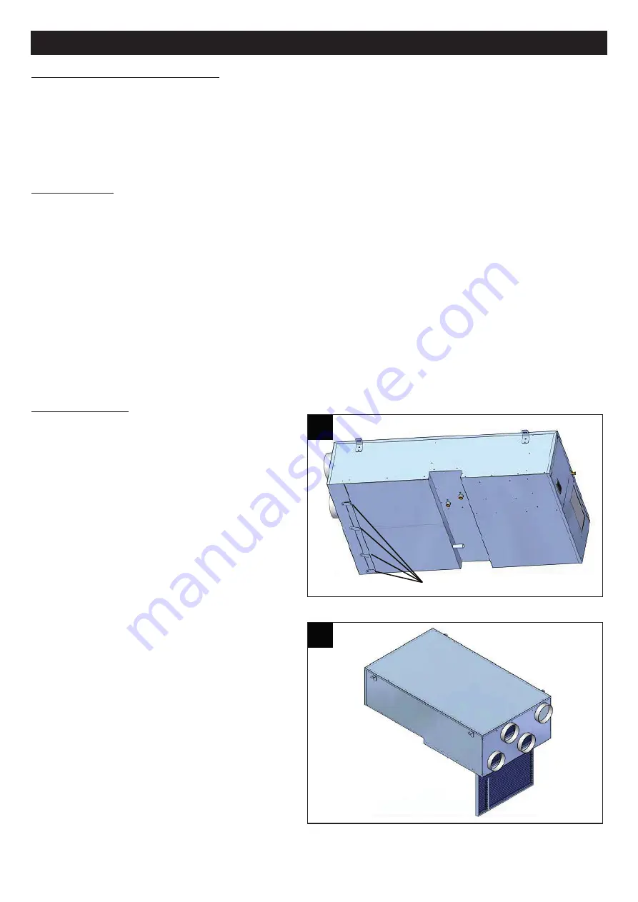
To  remove  the  filters  you  need  to  undo  the  screws
securing the filter bracket as shown in fig.43. 

After undoing the screws you can remove the filters as
in fig.44.

N.B.

The filter material can be reused after blow-cleaning or
vacuum-cleaning  it.  Because  of  the  high  efficiency  of
the  system,  however,  the  filter  material  cannot  be
regenerated more than three or four times, after which
the filter must be replaced.

49

ENGLISH

Viti staffetta blocca filtro

 43

 43

 44

 44

Filter bracket screws

Summary of Contents for VORT HRI 260 DH

Page 1: ...Libretto Istruzioni Instruction Booklet VORT HRI DH COD 5 471 084 696 23 05 2017...

Page 2: ...zia 24 Diagnosi e risoluzione dei problemi 25 Informazione importante per lo smaltimento ambientalmente compatibile 27 Before installing and using your product read these instructions carefully Vortic...

Page 3: ...nte o esterna variabile dal 40 al 90 N B l apparecchio progettato per operare all interno di un controsoffitto e o locale tecnico riscaldato e non adatto ad installazioni esterne e o in locali non ris...

Page 4: ...da una persona responsabile della loro sicurezza I bambini dovrebbero essere supervisionati per assicurarsi che non giochino con l apparecchio I bambini non devono giocare con l apparecchio La pulizi...

Page 5: ...ciclo frigorifero e la gestione della parte idronica ed aeraulica Il software provvede a gestire il funzionamento in base ad una sonda di temperatura e umidita ambiente collegate tramite porta RS 485...

Page 6: ...a temperatura umidit da installare a parete Scheda interfaccia seriale RS485 con protocollo MODBUS INSE per connettere la macchina a un sistema BMS Tabella dati tecnici Le prestazioni sono riferite al...

Page 7: ...ivi di sicurezza Funzionamento invernale e mezze stagioni compressore spento con aria esterna Impostando questa funzione l unita rinnova l aria ambiente con quella esterna attraverso il recuperatore d...

Page 8: ...scelta del sito di installazione devono essere presi in considerazione tutti i rischi originati da perdite accidentali di refrigerante N B Si raccomanda di prevedere un apertura nel controsoffitto di...

Page 9: ...da di alimentare l unit con una pompa dedicata E fortemente consigliato collegare l unit a monte del collettore dell impianto in modo da assicurare la corretta alimentazione idrica fig 9 N B Per un co...

Page 10: ...rdite di carico nell impianto aeraulico si dovr agire sulle griglie di taratura poste nelle varie bocchette di mandata e ripresa componenti non forniti dall Azienda operando sulla sezione di passaggio...

Page 11: ...ig 13 Scheda interfaccia seriale RS485 INSE Scheda seriale per interfacciamento al sistema di supervisione disponibile solo sistema di supervisione MODBUS RS485 L installazione della scheda permetter...

Page 12: ...amenti devono essere liberi da potenziale Contatto 13 43 chiuso unita in modalita INVERNALE Contatto 13 43 aperto unita in modalita ESTIVA I collegamenti devono essere liberi da potenziale fig 16 On o...

Page 13: ...state Contatto UA chiuso TA aperto unita in deumidificazione con aria neutra Contatto TA chiuso unita in deumidificazione con raffrescamento Contatto UA aperto TA aperto unita in sola ventilazione Fun...

Page 14: ...tensione 230 1 50 si raccomanda di interporre un sezionatore generale sulla linea di alimentazione Riferirsi allo schema elettrico per il dimensionamento fig 23 On off remoto Viene utilizzato per acc...

Page 15: ...pompa acqua al raggiungimento del set point Questa soluzione permette una importante riduzione della potenza elettrica assorbita quando il set point raggiunto o l unit in stand by fig 26 Pannello coma...

Page 16: ...gradi Celsius F gradi Fahrenheit BAR pressione in Bar PSI pressione in Psi Conteggio dell intervallo tra sbrinamenti Presenza di allarme lampeggiante Accesa durante l accesso al men funzioni Acceso f...

Page 17: ...lizzazione principale consente la modifica dei set point In modalit standard con sonda temperatura umidit ambiente permette di visualizzare le varie temperature 1 click La riga in basso visualizza tbf...

Page 18: ...r il fissaggio a muro e disponibile un adattatore per tastiere verticali V KIT fig 32 N B Per il collegamenti elettrici al pannello comandi remoto riferirsi allo schema elettrico fornito con l unita N...

Page 19: ...sso unit in fase di sbrinamento Acceso lampeggiante unit in fase di conteggio sbrinamento Allarme flusso acqua lampeggiante Pompa di circolazione attivata Accesa in chiamata ventilatori sulla sorgente...

Page 20: ...temperatura invernale e nella riga inferiore del display apparir la scritta SETH Nel caso in cui sono state configurati Ta e Ua i set point SETU SETC SETH e SETI non saranno visualizzati Pressione pe...

Page 21: ...za dal pavimento in posizione tale da non ricevere irraggiamenti o correnti d aria esterna Il collegamento elettrico deve essere eseguito come da schema precedentemente illustrato utilizzando cavi ele...

Page 22: ...odalit stand by Modalit inverno Per spegnere l unita in modalit inverno premere il tasto Il LED si spegne L unita commuta in modalit stand by Stand by Quando l unita spenta da tastiera o da pannello r...

Page 23: ...isplay visualizza LP codice di allarme nel display inferiore allarme bassa pressione HP codice di allarme nel display inferiore allarme alta pressione codice allarme nel display inferiore Il display i...

Page 24: ...lla tubazione acqua Controllare che i riscaldatori del carter siano alimentati e che funzionino correttamente mensilmente Controllare lo stato della batteria alettata se necessario pulire con aria com...

Page 25: ...ento E necessario pertanto Evitare reintegri d olio differente da quello specificato gi precaricato nel compressore Per macchine che utilizzano il fluido frigorigeno R134A o R410A nel caso in cui vi s...

Page 26: ...ua APBa Errore sonda temperatura ambiente PBa Si No Sonda guasta da sostituire Contattare assistenza tecnica APBr Errore sonda pre trattamen to PBr Si Si APbf Errore sonda antigelo PBf Si Si APBu Erro...

Page 27: ...na nuova apparecchiatura equivalente L utente responsabile del conferimento dell apparecchio a fine vita alle appropriate strutture di raccolta pena le sanzioni previste dalla vigente legislazione sui...

Page 28: ...and or false ceiling and is not suitable for installation outdoors and or in unheated rooms attics rooms communicating with the outdoor environment because condensate could form on the walls of the un...

Page 29: ...play with the appliance Cleaning and maintenance work on the appliance must not be performed by children without supervision Installation of the appliance in bathrooms where there are bath tubs or sho...

Page 30: ...correct supply of the water coil manages ventilation by means of an air quality sensor optional or directly by the timer built into the microprocessor manages the calibration damper displays machine...

Page 31: ...6 C relative humidity 65 outdoor air 35 C relative umidity 50 outdoor air flow rate 130 m3 h water inlet temperature 15 C nominal water flow rate 2 Outdoor air 5 C relative humidity 80 ambient tempera...

Page 32: ...pressor OFF with outdoor air By setting this operating mode the unit renews the indoor air with outdoor air by means of the very high efficiency heat recovery unit Air renewal with heating The compres...

Page 33: ...taken into consideration all risks arising from accidental loss of coolant N B Make sure you create an opening in the false ceiling of sufficient size to allow the unit to be removed completely for m...

Page 34: ...of the appliance the unit should be supplied by a dedicated pump You are strongly advised to connect the unit upstream of the system s manifold so as to ensure correct water supply fig 9 N B For corre...

Page 35: ...ced in the different delivery and intake spigots components not supplied by the company operating on the passage section of the grid higher cross section means lower pressure drop and higher air flow...

Page 36: ...RS485 INSE Serial circuit board for interfacing to the supervisory system available only the supervisory system MODBUS RS485 The PCB installation will allow the unit to be connected to a system with p...

Page 37: ...mode The connections must be potential free Contact 13 43 closed unit in WINTER mode Contact 13 43 open unit in SUMMER mode The connections must be potential free fig 16 Remote ON OFF Used for switchi...

Page 38: ...r operating mode RH contact closed RT open unit in dehumidification with neutral air RT contact closed unit in dehumidification with cooling RH contact open RT open unit in ventilation only Winter ope...

Page 39: ...ppliance is powered with a voltage of 230 1 50 a disconnector should be fitted on the power supply wire Please refer to the wiring diagram for sizing fig 23 Remote ON OFF Used for switching the unit O...

Page 40: ...er pump when the set point is reached This solution significantly reduces power consumption when the set point is reached or the unit is in stand by fig 26 Remote control panel All unit functions can...

Page 41: ...e le uscite Vf Pf Vfa Accesa se la macchina accesa e rappresenta lo stato di funzionamento Estivo o Invernale L icona HP e l icona LP sono accese lampeggianti in caso di allarme Alta o Bassa pressione...

Page 42: ...o della freccia sopra In modalit programmazione permette di scorrere i codici dei parametri o ne decrementa il valore Se premuto per 5 secondi rende possibile accendere o spegnere l unit in modalit es...

Page 43: ...poses of wall mounting an adapter is available for V KIT vertical keypads fig 32 N B For the electrical connections to the remote control panel please refer to the wiring diagram supplied with the uni...

Page 44: ...Vf Pf Vfa Accesa se la macchina accesa e rappresenta lo stato di funzionamento Estivo o Invernale L icona HP e l icona LP sono accese lampeggianti in caso di allarme Alta o Bassa pressione attivi ICO...

Page 45: ...ttivo o UOff se dovesse essere disattivo In modalit programmazione permette di scorrere i codici dei parametri o ne incrementa il valore In modalit standard permette di visualizzare le varie temperatu...

Page 46: ...out 1 2 to 1 5 m above the ground in a position in which it will not exposed to radiation or draughts of outdoor air The electrical connections must be made as per the diagram shown previously using s...

Page 47: ...s to stand by Winter mode To switch the unit off in winter mode press the button The LED switches off The unit switches to stand by Stand by When the unit is switched off from the keypad or from a rem...

Page 48: ...play high pressure alarm alarm code in the bottom display The bottom display shows the alarm code alternating with the normal view If an alarm is active the LP HP and Flow icons flash Alarm reset Pres...

Page 49: ...ilter installed on the water pipe Check that power is supplied to the guard heaters and that they work properly once a month Inspect the finned coil and if necessary clean with compressed air in the o...

Page 50: ...perating faults It is therefore necessary to Avoid topping up with fluid other than the specified fluid with which the compressor is pre charged For machines that use R134A or R410A if there are gas l...

Page 51: ...e totale assenza di aria nel circuito idraulico ed eventuale spurgo della stessa Verifica della portata d acqua all unit vedere catalogo tecnico Atdf Sbrinamento terminato per tempo massimo Si Si Warn...

Page 52: ...entally compatible disposal either directly or by participating in collective systems ENGLISH La Vortice Elettrosociali S p A si riserva il diritto di apportare tutte le varianti migliorative ai prodo...

Reviews: