Vollrath STOELTING CW 5 Plus - 37b Operator'S Manual Download Page 18

Section 4 : 

Maintenance

OPERATOR’S MANUAL

18

MAINTENANCE

Replacing the gaskets

CHECKING INTERVAL: 500 hours or quarterly

AUTHORISED OPERATOR: 1 Operator

TIME NEEDED: 5 minutes

TOOL: Non-metallic pointy tool

- Regularly check the integrity of the gaskets and substitute them if they are broken, worn or swollen.

- Only use original gaskets, made of food-safe rubber.

- The machine is supplied with a full set of spare gaskets and food grease tube.

  DO NOT PUT GASKETS IN THE INDUSTRIAL DISHWASHER, AS THE HIGH TEMPERATURES 

COULD DEFORM THEM, MAKING THEM UNUSABLE.

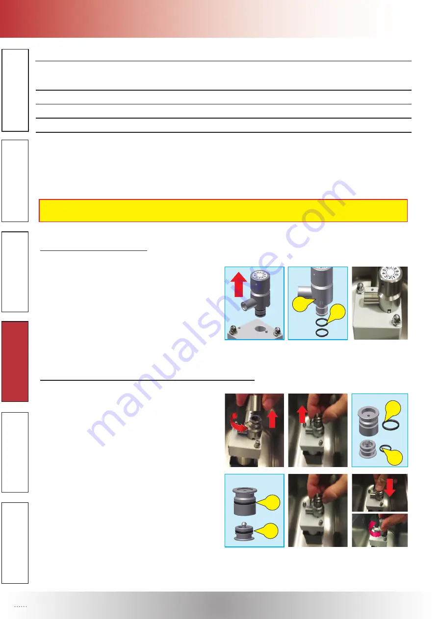
a) Gaskets of the air-regulator:

•  Remove the air-regulator from the pump cover. Re-

move the worn gaskets OR (1) from the air-regulator 

(2), using a non-metallic pointy tool, taking care not 

to scratch the gaskets’ seats.

• 

Remove all product residues from the seats and fit 

the new gaskets lubricating it with the food grease 

supplied.

•  Reassemble the air-regulator on the pump cover.

b) Gaskets of the valve socket and of the air regulating valve:

•  Screw the air-regulator knob counterclockwise and 

remove the valve socket vertically and air valve from 

the air regulator body. 

•  Remove the worn gaskets OR (3) from valve socket 

and air valve (4) using a non-metallic pointy tool, tak-

ing care not to scratch the gaskets’ seats.

• 

Remove  all  product  residues  from  the  seat  and  fit 

the new gaskets (5-6), lubricating them with the food 

grease supplied. Place the valve socket and reas-

semble air valve inside the air regulator body, turn 

clockwise the air regulator knob on air regulator body.

1

2

3

4

5

6

Summary of Contents for STOELTING CW 5 Plus - 37b

Page 1: ...Operator s Manual Cream whipper model CW 5 Plus 37b Translation of the original instructions...

Page 2: ...Section 1 Introduction OPERATOR S MANUAL 2 INTRODUCTION...

Page 3: ...TANT RULES 7 D Rinsing Phase and Washing procedure 8 E Disassembling Primary Parts 9 10 F Disassembling Secondary Parts 10 11 G Cleaning and Sanitizing Disassembled Parts 11 H Cleaning Machine 12 L As...

Page 4: ...Section 1 Introduction OPERATOR S MANUAL 4 INTRODUCTION 1 2 4 6 5 7 9 10 11 13 17 18 12 19 8 15 16 14 3 20...

Page 5: ...l CW 5 PLUS 37b Net weight lbs kg 77 35 Dimensions width height depth 10 25cm 19 49cm 18 47cm Hopper Volume max gal L 1 32 5 Max ambient temperature F C 95 35 Compressor Number Btu hr 1 290 Coolant ga...

Page 6: ...o about 3 oz By pushing the button 7 after P2 parameter it is possible to set a value between 1 and 90 for the automatic dispensing of the whipped cream The setting of value 1 corresponds to a 0 5 sec...

Page 7: ...range of 1 to 90 The setting of value 1 corresponds to a 0 5 sec dispensing up to a maximum value of 90 which corresponds to a 45 sec dispensing The factory set value is 7 about 1 oz Having pressed t...

Page 8: ...pro priate container placed under the dispensing faucet D4 Press the DISPENSING button again to stop the continuous functioning when the cream container is empty D5 Remove the cream container and wash...

Page 9: ...and remove it vertically E4 Pull the valve assembly out vertically E5 Pull the air regulator body out vertically from the pump cover E1 E1 E2 E2 E3 E3 E3 E3 E4 E4 E4 E4 E5 E5 E5 E5 E Disassembling Pri...

Page 10: ...gaskets seats F4 Remove the gasket from the cream dispenser using a non metallic pointy tool taking care of not damaging the gasket seat E6 E6 E6 E6 E7 E7 E7 E7 E8 E8 F Disassembling Secondary Parts F...

Page 11: ...from the valve socket using a non metallic pointy tool taking care of not damaging the gasket seating F Disassembling Secondary Parts F5 F5 F5 F5 F5 F5 F7 F7 F8 F8 G Cleaning and Sanitizing Disassemb...

Page 12: ...rgent solution and the big barrel brush provided clean the hole of the outlet tube by dipping the brush in the solution and brushing the inside of the hole H Cleaning Machine The exterior of the machi...

Page 13: ...e valve L3 Insert the O Ring gaske on the valve socket L4 Assemble the air valve with the valve socket Reassembling of the labyrinth L5 Insert the 2 O Ring gaskets on the labyrinth Reassembling of the...

Page 14: ...nth labyrinth tube and faucet M4 Insert the labyrinth into the hole on the outlet tube Insert the fixing end of the labyrinth in the pump cover M5 Insert the fixing rod in the hole of the pump cover M...

Page 15: ...positioning of the cream container and lid M10 Insert the cream aspiration tube in the hole of the air regulator M10 Push the tube to fix it properly in the air re gulator M11 Place the cream contain...

Page 16: ...AND DRUG ADMINISTRATION REQUIRE THAT ALL CLEANING AND SANITIZING SOLUTIONS USED WITH FOOD PROCESSING EQUIPMENT BE CERTIFIED FOR THIS USE WHEN SANITIZING THE MACHINE REFER TO LOCAL SANITARY REGULATION...

Page 17: ...o Maintain the dispensing active until the washing solution contai ned in the cream container is used up N4 Pour solution into the cream container N5 Place a suitable container under the dispensing fa...

Page 18: ...the air regulator 2 using a non metallic pointy tool taking care not to scratch the gaskets seats Remove all product residues from the seats and fit the new gaskets lubricating it with the food grease...

Page 19: ...labyrinth tube inside the hole of the dispenser faucet Following screw clockwise the nozzle on the cream dispenser e Gaskets of the labyrinth Turn the nozzle clockwise and remove the cream dispenser...

Page 20: ...Faulty temperature probe interrupted or out of tolerance and or related wiring damaged Contact the Technical Assistance Service PE alarm warning The tank temperature probe signals a tem perature lowe...

Page 21: ...chesandresidualcurrent operatedcircuitbreakers cut outs on theelectricalsystem upstreamofthe socket are closed Ifnot beforeclosingthem makesure thatnooneiscarryingoutelectrical repairs NO YES A fuse d...

Page 22: ...hoose another kind of cream YES Disassemble and clean it as described in Sections F G The refrigerating SYSTEM is damaged NO YES Contact the technical assistance service YES NO YES NO MACHINE REPEATED...

Page 23: ...ibed in Sections F G YES The CREAM ASPIRATION tube is obstructed NO YES The pump is damaged NO Disassemble the CREAM ASPIRATION tube and clean it as described in Sections F G YES Contact the technical...

Page 24: ...environmentistoohighandthere is insufficient condensation The air condenser is blocked Restore the operating temperature as indicated in the manual in sec B Speci fications YES Ask the Technical assis...

Page 25: ...Section 5 Troubleshooting OPERATOR S MANUAL 25 TROUBLESHOOTING...

Page 26: ...4 011 EP1 FOOD GREASE TUBE 1 P02 010 GASKET O RING 3043 2 P02 013 GASKET O RING 2050 1 P04 116 WHITE NOZZLE 1 P04 118 WHITE NOZZLE 1 P04 382 DISPENSING FAUCET 1 P05 141 LID 1 P05 142 DRIP TRAY 1 P07 4...

Page 27: ...E SOCKET 1 A03 049 AIR REGULATOR KNOB 1 A03 217 AIR REGULATOR BODY 1 A05 003 AIR REGULATION SPRING DIM D21800 1 A06 305 AIR REGULATOR ASSEMBLY 1 A11 033 FIXING ROD 1 A11 036 CREAM ASPIRATION TUBE 1 P0...

Page 28: ...updated 04 02 2020...

Reviews: