


18
5.1 GAS SUPPLY INSTALLATION
Inspect the entire installation including the gas meter,
test for tightness and purge. Refer to BS 6891 (I.S. 813
in ROI) for specifi c instruction.
5.2 THE HEATING SYSTEM
The appliance contains components that may become
damaged or rendered inoperable by oils and/or debris
that are residual from the installation of the system,
consequently it is essential that the system be fl ushed
in accordance with BS 7593 Code of Practice and the
following instructions.
5.3 INITIAL FILLING OF THE SYSTEM
Remove appliance casing as described in 4.7.1, identify
the automatic air release valves (AAV) and loosen the
dust cap/s by turning the cap anti-clockwise one full turn.
Ensure all manual air release valves located on the heat-
ing system are closed. Proceed to fi ll the system via the
feed and expansion tank and begin venting all manual
air release valves, starting at the lowest fi rst.
Once the system has been fi lled. Inspect the system for
water soundness, rectifying any leaks.
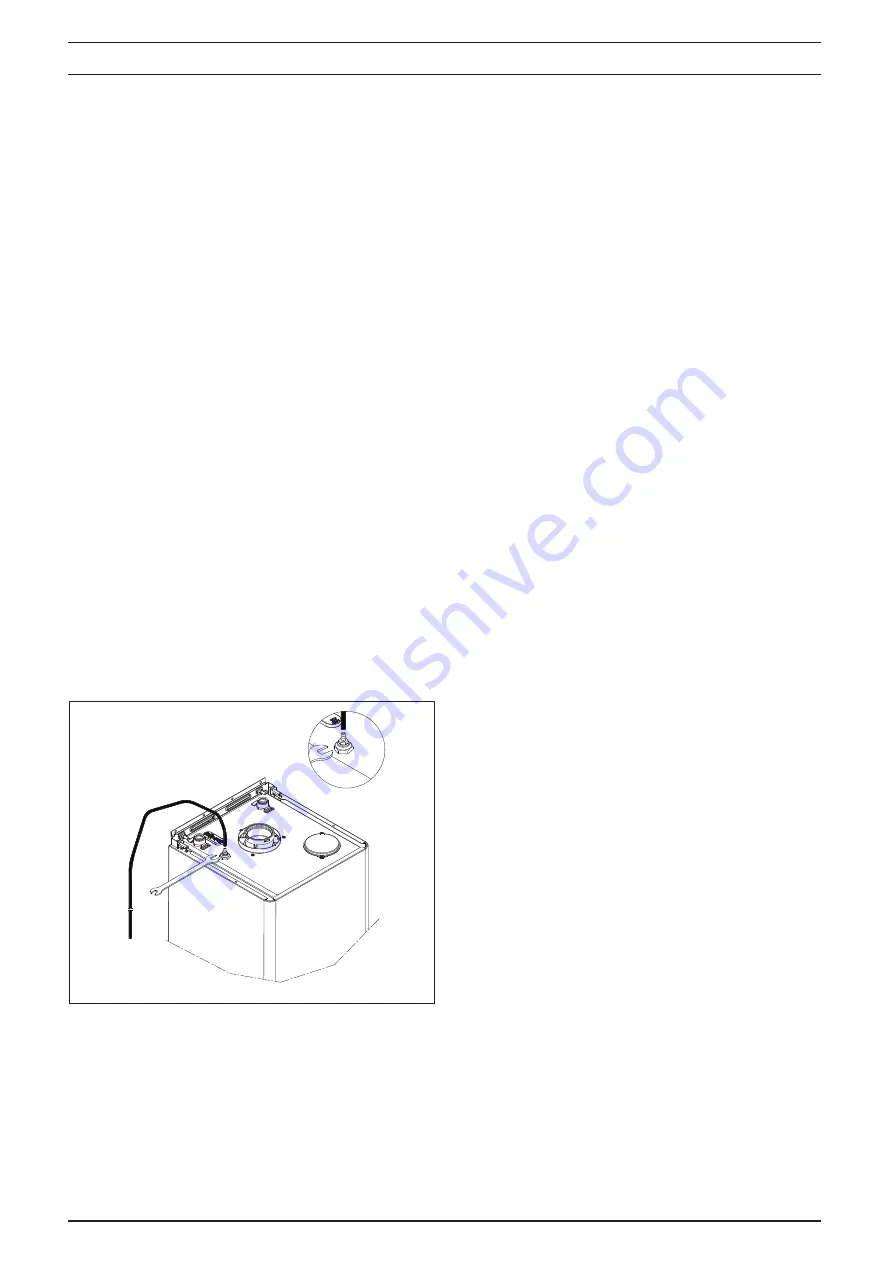
5.3.1 MANUAL AIR RELEASE (Fig. 22)
When the boiler has been fi lled for the fi rst time or the
system has been drained and refi lled, it will be necessary
to release any air that may have become trapped within
the appliance heat exchanger.
Slacken the bleed screw until water is released and then
close.
IMPORTANT, THERE ARE NO OTHER MANUAL AIR
RELEASE VALVES LOCATED ON THE APPLIANCE.
5.4 INITIAL FLUSHING OF THE SYSTEM
The whole of the heating system must be fl ushed both
cold and hot as detailed in 5.8. Open all radiator and/or
heating zone valves.
Drain the boiler and system from the lowest points.
Open the drain valve full bore to remove any installation
debris from the boiler prior to lighting.
Refi ll the boiler and heating system as described in 5.3.
5.5 PRE-OPERATION CHECKS
Before attempting the initial lighting of the appliance, the
following checks must be carried out:
Ensure all gas service valves from the meter to the
appliance are open and the supply pipe has been
properly purged;
Ensure the proper electrical checks have been car-
ried out, (see 7.8) particularly continuity, polarity, and
resistance to earth;
Ensure the 3 AMP fuse – supplied with the appliance
– has been fi tted.
Ensure the system has been properly fi lled and vented.
Ensure the fl ue system has been fi tted properly and in
accordance with the instructions.
out, (see 7.8) particularly continuity, polarity, and resist-
ance to earth;
Ensure the 3 AMP fuse – supplied with the appliance
– has been fi tted.
Ensure the system has been properly fi lled and vented.
Ensure the fl ue system has been fi tted properly and in
accordance with the instructions.
5.6 INITIAL LIGHTING
Ensure the electrical supply to the appliance is switched
on. Ensure any external controls are switched to an ‘ON’
position and are calling for heat.
Move the selector switch to the ON position, the appliance
will now operate as described in 1.2.
Should the appliance fail to ignite, refer to 5.6 and/or
section 7 (mode of operation & faultfi nding).
NOTE
When power is restored to the PCB and/or the PCB
is powered for the fi rst time, the appliance will enter
a 2-minute purge cycle whereby only the pump will
run for 15-seconds then off for 15-seconds.
5.7.1 CHECKING GAS PRESSURE AND COMBUS-
TION ANALYSIS
The appliance is factory set so should require no addi-
tional adjustment once installed. However to satisfy the
requirements of GSIUR 26/9 (I.S. 813 ROI), it will be
necessary to gas rate the appliance using the gas meter
that serves the appliance and carry out a combustion
analysis check in accordance with BS 7967 (UK) to en-
sure that correct combustion is occurring, see fl ow chart
on page 38.
Additionally, if the gas valve has been adjusted, repla-
ced, or the appliance has been converted for use with
another gas type, then it becomes necessary to carry
out a combustion analysis check to ensure that correct
combustion is occurring.
If there are no means to carry out a combustion analysis
check, then it will not be possible to complete the com-
missioning procedure.
Details on how to carry out the combustion analysis can
be found in section 7.
IMPORTANT
It’s imperative that a suffi cient dynamic – gas – pres-
sure is maintained at all times. Should the dynamic
gas pressure fall below an acceptable level, the ap-
pliance may malfunction or sustain damage.
SECTION 5 COMMISSIONING
Fig. 22


