


29
7.4.4
ABSOLUTE MIN FAN SPEED - LP
Select the parameter LP by turning the DHW
temperature control; push MODE button, it is
possible to set the absolute min fan speed that is
related to gas type and boiler output. Modify this
parameter only if strictly necessary.
The value is shown on the display as rpm/100 (i.e.
3600/100 = 36). The set value automatically
modifies the min value of parameter 24.
7.4.5
START-UP FAN SPEED - SP
Select the parameter SP by turning the DHW
temperature control; push MODE button, it is
possible to set the start-up fan speed. Modify this
parameter only if strictly necessary.
The value is shown on the display as rpm/100 (i.e.
3600/100 = 36).
7.4.6
GAS VALVE MAXIMUM SETTING - HH
Select the HH parameter by turning the DHW
temperature control; the boiler starts at the maxi-
mum power, the CO
2
reading should be as shown
in the table below(for LPG see 9.2.
If the CO
2
reading is correct, pass to gas valve
minimum setting (7.4.7). If the CO
2
reading is
incorrect, the maximum gas pressure must be
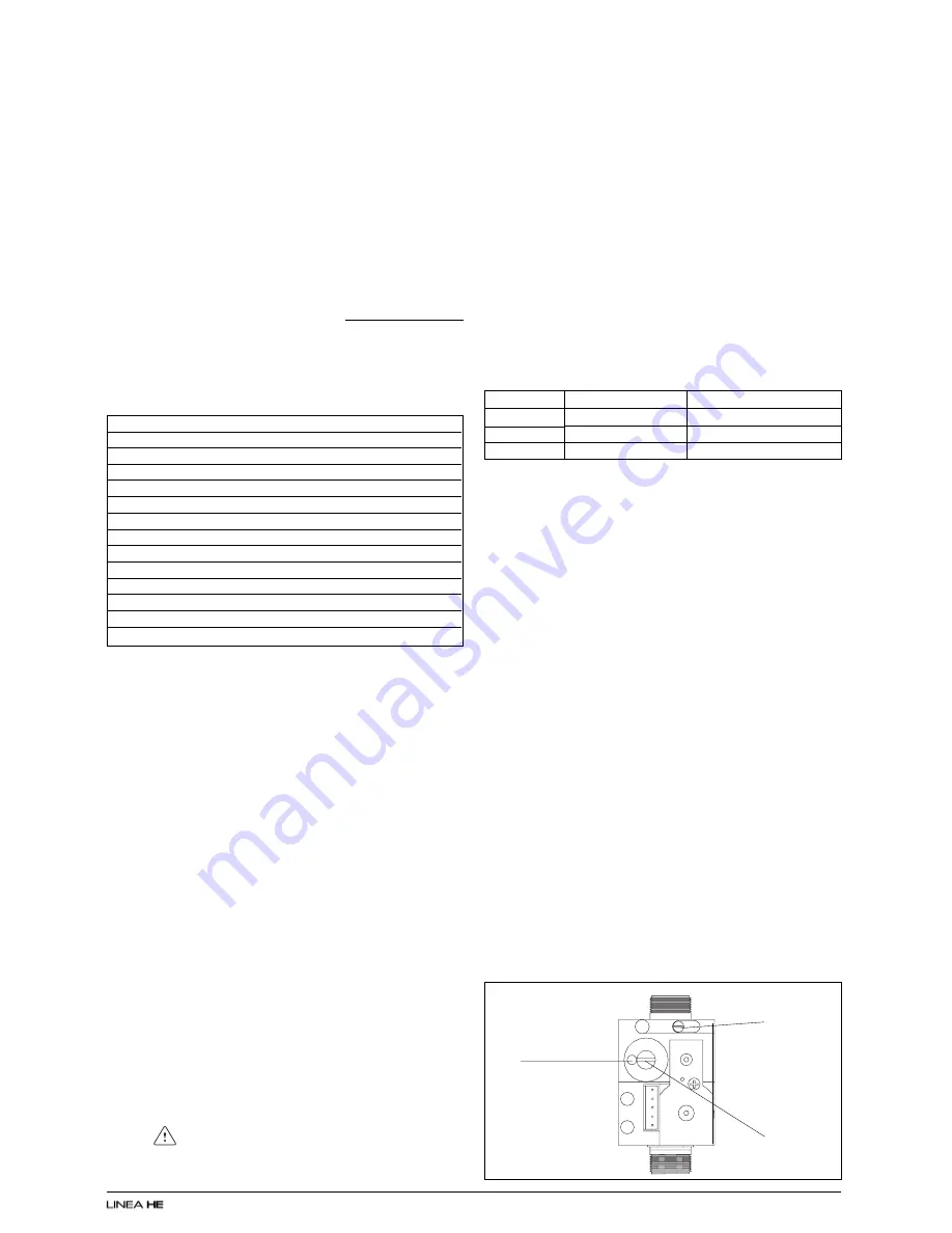
adjusted as follows:
●
using a suitable screwdriver, very slowly turn
the maximum adjustment screw (see fig. 43) –
clockwise to decrease, counter clockwise to
increase – until the correct value is displayed on
the CO
2
analyser (allow time for the analyser to
stabilise).
IMPORTANT
A GAS SOUNDNESS CHECK MUST BE CAR-
RIED OUT.
7.4.7
GAS VALVE MINIMUM SETTING - LL
Select the LL parameter by turning the DHW
temperature control. The boiler starts at the mini-
mum power, the CO
2
reading should be as shown
in the table above.
If the CO
2
reading is correct, pass to gas valve
final setting (7.4.8). If the CO
2
reading is incorrect,
the minimum gas pressure must be adjusted as
follows:
●
using a 2,5 Allen key, very slowly turn the mini-
mum adjustment screw (see fig. 43) – clockwise
to increase, counter clockwise to decrease - until
the correct value is displayed on the CO
2
analyser
(allow time for the analyser to stabilise).
Fig. 43
Maximum
screw
Minimum
screw
7.4
ADJUSTING MODE & ADJUSTING THE GAS VALVE
THE GAS VALVE MUST BE SET-UP OR AD-
JUSTED WITH THE AID OF A PROPERLY CALI-
BRATED FLUE GAS ANALYSER.
Isolate the appliance from the electrical supply
and remove the appliance casing as described in
4.7.1. Set the flue gas analyser to read CO
2
and
insert the probe into the flue analysis test point (
A,
B
fig. 40). Restore the electrical supply to the
boiler and switch on the boiler.
To adjust the gas valve you must first access the
adjusting mode. This mode is only accessible in
STANDBY mode. To access the adjusting mode:
push INFO and MODE buttons at the same time
for 10 seconds to enter the adjusting menu.
The display shows “CodE” (see fig. 41). Push
MODE button and select the adjust parameters
password by turning the DHW temperature control
and confirm it by pushing MODE button. The
following functions are available in this mode.
* Only if outside sensor connected.
7.4.1
GAS TYPE SETTING - 1
Select the parameter 1 by turning the DHW tem-
perature control; push MODE button, it is possible
to set gas type: 1(natural gas) - 2 (LPG), by turning
the DHW temperature control. Push MODE buttom
to store the gas type selected.
7.4.2
BOILER OUTPUT - 2
Select the parameter 1 by turning the DHW tem-
perature control; push MODE button, it is possible
to set the boiler output: 26 (25 kW) - 30 (30 kW) -
34 (35 kW), by turning the DHW temperature
control. Push MODE buttom to store the gas type
selected.
ATTENTION
Gas type and boiler output
must be
according to
the boiler design specification.
Vokera has no responsability if the gas type and
boiler output are set not according to the appliance
specification.
7.4.3
ABSOLUTE MAX FAN SPEED - HP
Select the parameter HP by turning the DHW
temperature control; push MODE button, it is
possible to set the absolute max fan speed that is
related to gas type and boiler output. Modify this
parameter only if strictly necessary.
The value is shown on the display as rpm/100 (i.e.
3600/100 = 36).
For Linea 28HE and 32HE it is necessary to
adjust the parameter 23 (see 7.4.9).
Power
Linea 28HE
Linea 32HE
Linea 36HE
CO
2
@ min
9.3%
9.0%
9.0%
CO
2
@ max
9.0%
9.0%
9.0%
Par.
Action
01
set gas type
02
set boiler power
10
set DHW type
03*
type of building
45*
climatic curve selection
HP
absolute max fan speed selection
LP
absolute min fan speed selection
SP
start-up fan speed
HH
force burner at max power
LL
force burner at min power
MM
force burner at medium power
23
max output CH (fan speed)
24
min output CH (fan speed)
Compensation
pipe connection


