P24AL & P34AL Service Manual
SERVICING OPERATIONS
12/2016
9-6
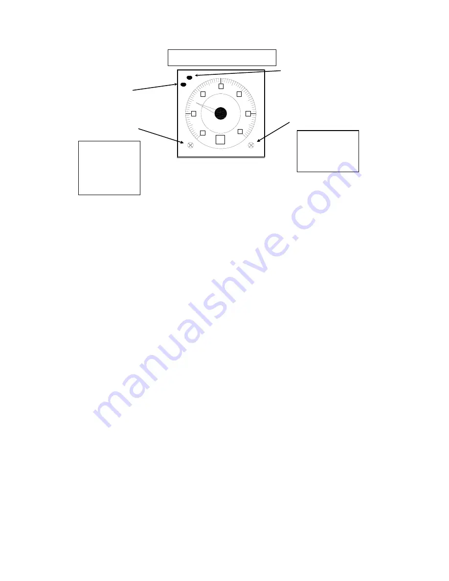
Figure 9-4
Thawing Timer (2TR)
Suggested Condenser Cleaning.
Any brush or cleaning tool should be sized accordingly so as not
to damage the tubes during cleaning. The cleaning tools should be rotated at the specified speed for
the particular tool used. The tubes should be kept wet during cleaning. After cleaning the tubes
should be flushed thoroughly and all foreign material removed. Contact your distributor or Vogt’s
Service Department to obtain the proper cleaning tools.
The following is the condenser cleaning procedure:
1.
Make sure ample room is provided for removing the condenser heads and using the mechanical
cleaning equipment.
2.
Order replacement cover gaskets for use at the time of reassembly.
3.
Disconnect and lock-out power to the ice machine, compressor and auxiliary equipment.
4.
Disconnect water piping and drain the condenser. Generally additional water can be drained by
loosening the cover (heads) and separating the covers from the condenser end.
5.
Remove the heads bolts and gasket completely.
6.
Inspect the tubes for excessive corrosion and possible ammonia leaks to determine whether or not
further cleaning is feasible.
7.
Clean the inside of each tube as well as possible, being careful not to damage the tube. Follow
the instructions for the particular tool being used.
8.
Flush each tube with water to remove all loose material to prevent contamination of the cooling
tower and sump.
9.
Clean the ends of the tube sheets, so the new gasket will seal properly.
10.Install the replacement gasket. Make sure the gasket does not cover the tube ends.
11.Install the end covers (heads) and fasten securely in place with the head bolts. It is recommended
that a anti-seize compound be applied to the bolt and nut threads to prevent rusting and ensure
ease of removal at the next cleaning.
12.Reconnect the water piping, turn on the power. Check for leaks by turning the power on to the
condenser pump allowing it to run.
13.Turn the power ON to the compressor and wait for the crankcase heater to warm-up the
compressor before starting the machine.
Allen Bradley Timer (White)
0
2
4
6
8
10
12
RANGE
UNIT
POWER
UP
Min
Power Light (green)
Light blinks while "timing"
Light solid when "timed out"
Unit Adjustment
sec
min
hrs
10h
Units: Set to “min”
Range: Set to
“0 to 12”
Time Range
Adjustment
0 - 1.2
0 - 3
0 - 12
0 - 30
Up Light (red)
Light off while "timing"
Light solid when "timed out"
Summary of Contents for P-24AL
Page 1: ...12 2016 P 24AL P 34AL TUBE ICE MACHINE Service Manual 5000 ...
Page 10: ...P24AL P34AL Service Manual TABLE OF CONTENTS 12 2016 vi ...
Page 15: ...P24AL P34AL Service Manual INTRODUCTION 12 2016 1 5 Figure 1 2 P24AL Right Side ...
Page 16: ...P24AL P34AL Service Manual INTRODUCTION 12 2016 1 6 Figure 1 3 P24AL Back Side ...
Page 17: ...P24AL P34AL Service Manual INTRODUCTION 12 2016 1 7 Figure 1 4 P24AL Left Side ...
Page 18: ...P24AL P34AL Service Manual INTRODUCTION 12 2016 1 8 Figure 1 5 P34AL Front Side Control Panel ...
Page 19: ...P24AL P34AL Service Manual INTRODUCTION 12 2016 1 9 Figure 1 6 P34AL Right Side ...
Page 20: ...P24AL P34AL Service Manual INTRODUCTION 12 2016 1 10 Figure 1 7 P34AL Back Side ...
Page 21: ...P24AL P34AL Service Manual INTRODUCTION 12 2016 1 11 Figure 1 8 P34AL Left Side ...
Page 22: ...P24AL P34AL Service Manual INTRODUCTION 12 2016 1 12 ...
Page 62: ...P24AL P34AL Service Manual START UP OPERATION 12 2016 5 8 ...
Page 84: ...P24A P34A Service Manual TROUBLESHOOTING 12 2016 8 12 ...
Page 110: ...P24AL P34AL Service Manual SERVICING OPERATIONS 12 2016 9 26 ...
Page 126: ...P24AL P34AL Service Manual TABLES CHARTS 12 16 16 11 8 ...
Page 130: ...P24AL P34AL Service Manual INDEX 12 2016 12 4 ...
Page 131: ...Appendix A ...
Page 134: ......
Page 136: ...i ...
Page 137: ...ii ...
Page 138: ...1 ...
Page 139: ...2 ...
Page 140: ...3 ...
Page 141: ...4 ...
Page 142: ...5 ...
Page 143: ...6 ...
Page 144: ...7 ...
Page 145: ...8 ...
Page 146: ...9 ...
Page 147: ...10 ...
Page 148: ...11 ...


