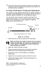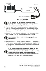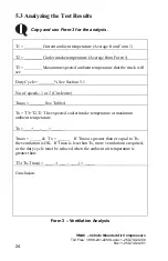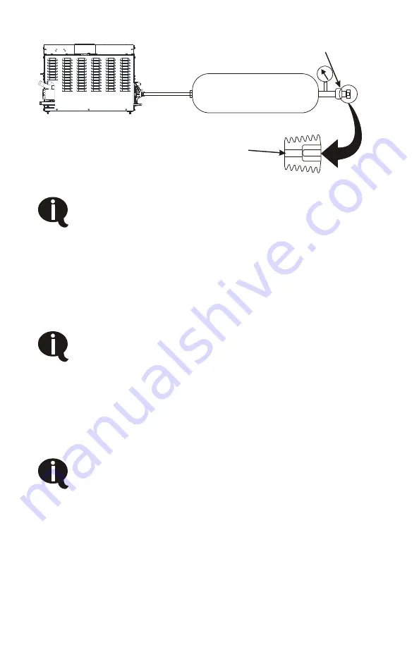
Compressor
Air receiver
Ball valve
Orifice drilled in plug
Pressure gauge
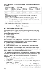
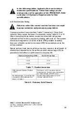
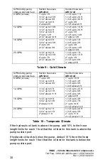
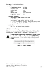
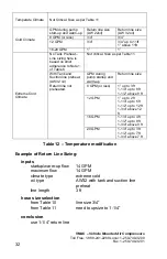
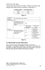
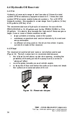
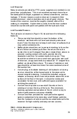
Figure 12 – Test setup
If the air pressure drops below 100 psi, increase
hydraulic flow to bring the pressure back up. Do not
exceed hydraulic flow specifications
9. Test the system for 1 hour at the maximum duty cycle. Make
sure that you can read the temperature for the duration of the
test without disturbing the system by opening cabinets or other
functions.
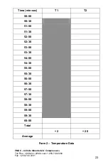
10. Record “T
2
” every 30 seconds during the last 10 minutes of the
test. Record “T
1
” at the 50 minute and 60 minute marks.
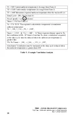
Copy and use Form 2 on the following page for your
calculations.
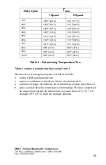
11. For the analysis, “T
1
” is the average of the two “T
1
” readings and
“T
2
” is the average of the 20 “T2” readings taken in step 10. “T
3
”
is the maximum ambient temperature to which the vehicle will be
exposed.
If the system shuts down at any point during the test,
check the display box for messages and cross-
reference them to the table in the Owner’s Manual. If th
system shuts down due to an over-temperature
condition, check all oil levels, improve ventilation an
repeat the test once the syste
e
d
m has cooled.
VMAC – Vehicle Mounted Air Compressors
Toll Free:
1-888-241-2289 Local: 1-250-740-3200
Fax: 1-250-740-3201
22

