background image


Viz SDI I/O Module Operating Instructions 

`13 


C

OLOR 

T

AB


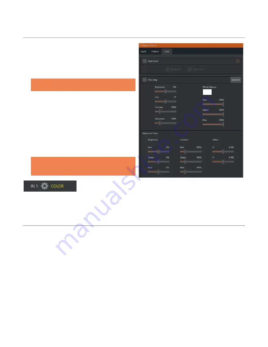
The 

Color

  tab provides an extensive set of tools for 

adjusting the color characteristics of each video 

channel. 

Choosing 

Auto Color

  automatically adapts color 

balance as lighting conditions change over time.  

Note: Proc Amp adjustments are applied after Auto 

Color processing. 

By default, each camera with 

Auto Color

  enabled is 

processed by itself.  Enable 

Multicam

  to process 

multiple cameras as a group. 

To apply 

Multicam

 processing to a source without its 

own colors being evaluated, checkmark 

Listen Only

.   

Or enable 

Listen Only

 for all 

Multicam

 group members 

except one to make that source the ‘master’ color 

reference. 

Note: Custom settings in the Color tab trigger a 

COLOR notification message that appears in the 

footer below the viewport of the channel (Figure 13)


FIGURE 13 


SECTION 2.2


FIRST LAUNCH & I/O CONFIGURATION 

The physical SDI connectors can be flexibly assigned as either inputs or inputs.  Alternative layouts for the 

connectors are available in the 

Configure Viz SDI I/O Connectors

 panel (Figure 14), which is normally shown 

on first launch, but which can also be selected to open on exiting the 

Live Desktop

FIGURE 12


Summary of Contents for Viz SDI IO

Page 1: ......

Page 2: ...been taken in the preparation of this document to ensure that it contains accurate and up to date information the publisher and author assume no responsibility for errors or omissions Nor is any liab...

Page 3: ...Section 1 5 Networking 7 CHAPTER 2 USER INTERFACE 8 Section 2 1 The Desktop 8 2 1 1 Configure Channels 9 Section 2 2 First Launch I O Configuration 13 2 2 1 Configure IO Connectors 14 Section 2 3 Tit...

Page 4: ...4...

Page 5: ...2 OVERVIEW Commitments and requirements can change from production to production A powerful versatile platform for multi source production and multi screen delivery workflows this module can quickly...

Page 6: ...ocal power is unreliable or noisy Surge protection is especially important in some locales Power conditioners can reduce wear on power supplies and other electronics and provide a further measure of p...

Page 7: ...SECTION 1 5 NETWORKING Generally simply connecting a suitable cable from one of the two Gigabit Ethernet ports on Viz SDI IO s backplane is all that is required to add it to a local area network LAN I...

Page 8: ...esktop interface is shown below and provides very useful remote monitoring options in addition to configuration and control features FIGURE 2 The Desktop interface includes dashboards running across t...

Page 9: ...ny NDI or SDI connector configured as an input the latter are shown in the Local group a webcam or PTZ camera with compatible network output or even an input from a suitable external A V capture devic...

Page 10: ...s a PTZ camera with NDI network video output can be directly selected The Video Source drop down menu contains an Add Media item to let you select a video file and Add IP Camera menu item Figure 5 FIG...

Page 11: ...og suited to the particular source device you wish to add such as one of the numerous supported PTZ camera brands and models Note After adding an IP source you must exit and restart the software for t...

Page 12: ...options supported by the device are provided in a menu at right Quad link selections list the four associated SDI output numbers that will be used for reference See Appendix A Key Fill Connections for...

Page 13: ...source without its own colors being evaluated checkmark Listen Only Or enable Listen Only for all Multicam group members except one to make that source the master color reference Note Custom settings...

Page 14: ...lect either the IO Configuration or Genlock tabs according to your need The IO Configuration tab makes it a simple matter to select presets using graphic representations that depict the connector layo...

Page 15: ...Genlock connector on the backplane Note The unit can use SD Bi level or HD Tri level reference If the Genlock switch is disabled the unit operates in an internally managed free running mode instead In...

Page 16: ...the free NDI Tool pack and enable the KVM button overlaid at upper left when you move the mouse pointer over the screen Hint Note that Studio Monitor s KVM toggle button can be relocated to a more co...

Page 17: ...the Notifications panel is opened you will see the performance levels of your CPU Memory GPU Drive and NIC 1 network interface controller WEB BROWSER In addition to the remote control features provid...

Page 18: ...ame and path for still image grabs are set in the Configure Channel panel 4 Full screen 5 Overlays GRAB FIGURE 20 A Grab Input tool is located in the lower right corner below the monitor for each chan...

Page 19: ...d moving the slider provided at right double click this control to reset it to the default 0dB value RECORD The Record button is also located in the lower right corner of the dashboard Figure 26 Click...

Page 20: ...the primary screen the Display widget offers a variety of layout options to let you viewing channels individually or in groups as well letting you configure a second monitor Figure 27 FIGURE 27 Wavefo...

Page 21: ...on IP workflows over Ethernet networks NDI allows systems and devices to identify and communicate with each other and to encode transmit and receive high quality low latency frame accurate video and a...

Page 22: ...Viz SDI I O Module Operating Instructions...

Reviews: