


12
AWG20
AWG26
Purple
Blue
Orange
Brown
Green
Yellow
DO+:
DO-:
RS485+:
RS485-:
DI+:
DI-:
+
DO+(5V)
DO2-
DI2+
DI1+
DI-
RS485-
RS485+
DO1-
AC24V
AWG20
DC12V
-
AC/DC pwr+
AC/DC pwr-
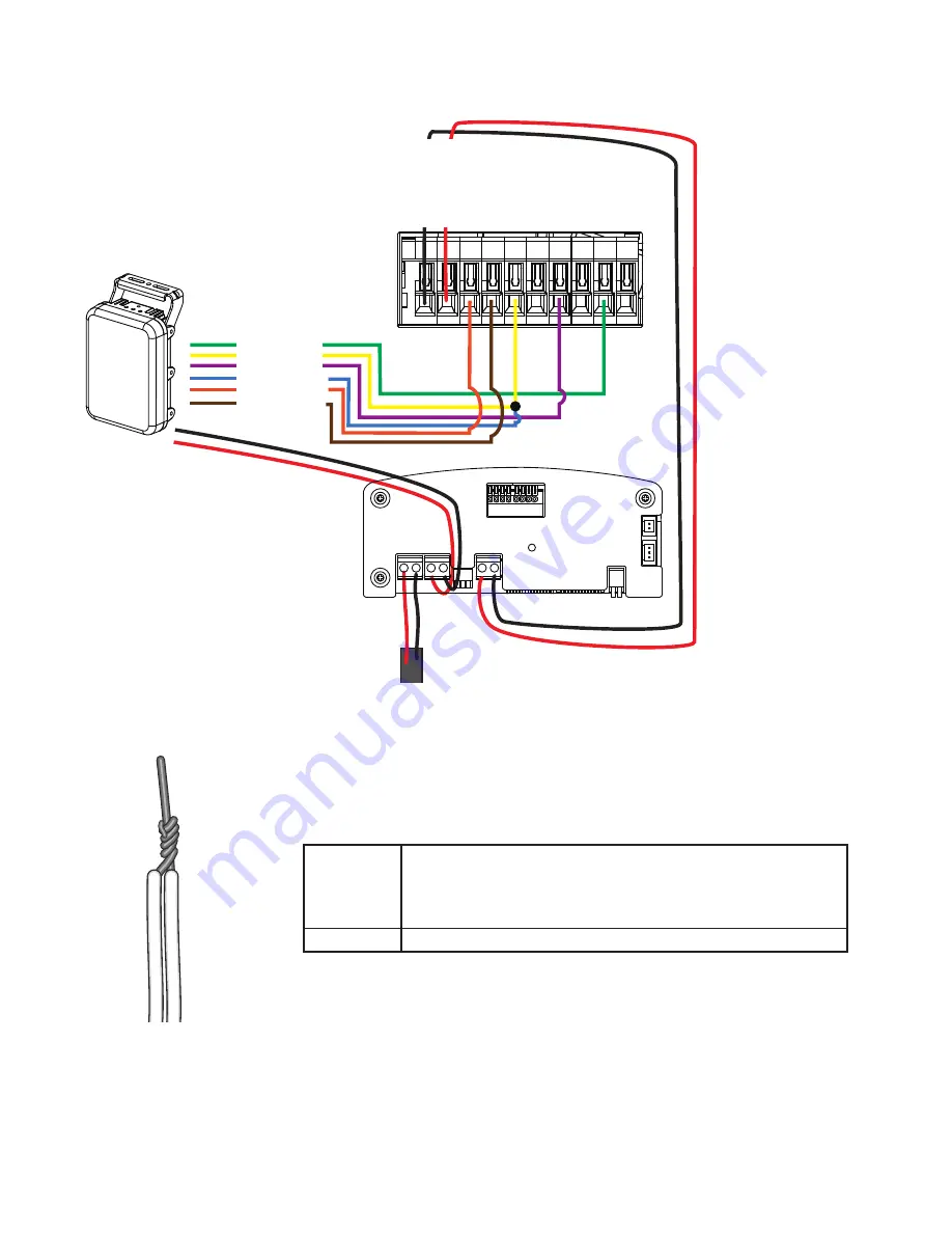
Camera
terminal block
A sample connection diagram consisting of CaMate's IR illuminators and the camera is
shown below. Please refer to your camera's documentation if your camera comes with
different pinouts.
DO-
DI-
14.
You can connect the ground wires together and connect them to the DI- ground pin
on the terminal. Use a small flat blade screwdriver to press the lever on the terminal block.
The default for the DI status is listed below:
DI
Normal: High
Current Status:
> High - Day mode.
> Low - Night mode (IR is on)


