background image


26 

Ventilation 

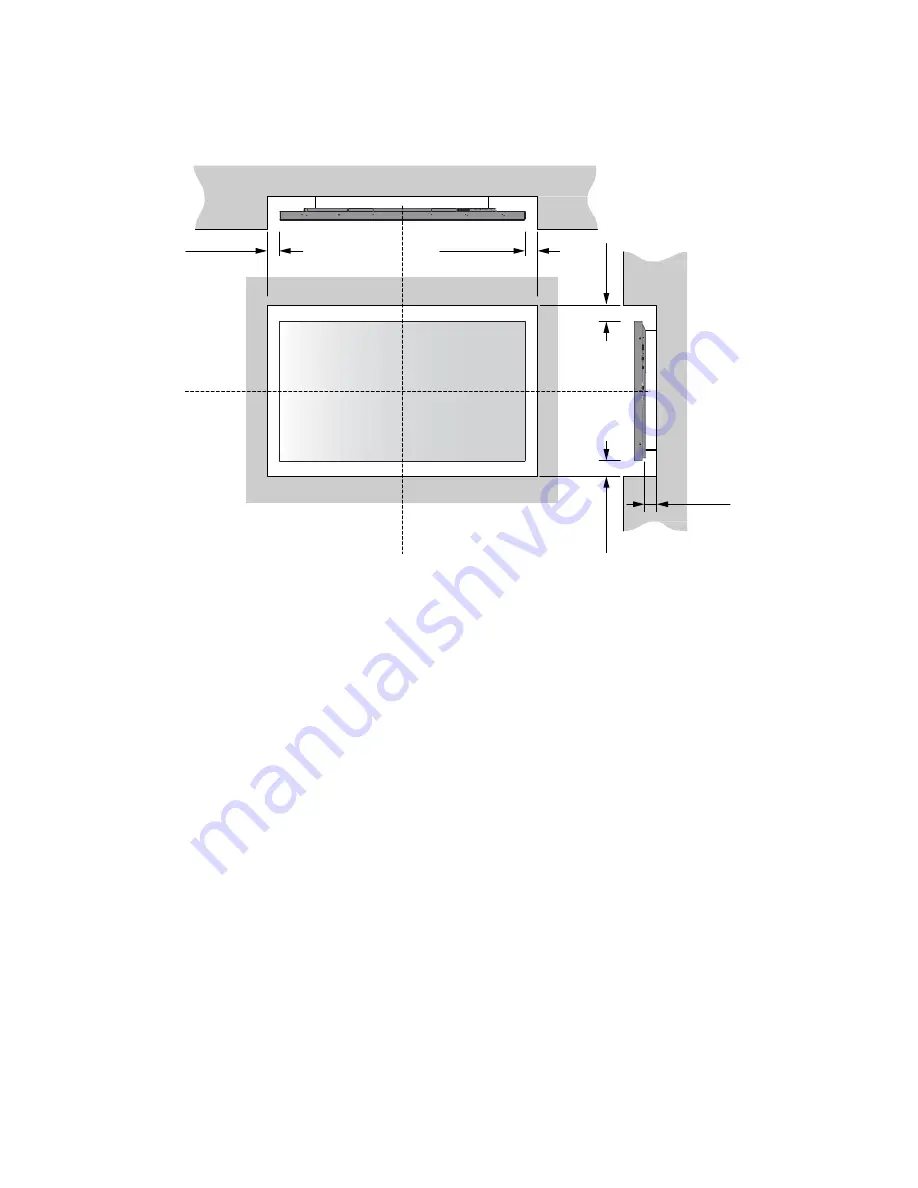
If you are mounting the display in an enclosure, leave sufficient space on all sides between it and surrounding objects, 
as shown in Figure 3-1. This allows heat to disperse, maintaining the proper operating temperature. 


Figure 3-1. Ventilation Requirements for Enclosure Mounting 


Wall 

50 mm (2

"

50 mm (2

"

Wall 

50 mm (2

"

50

 mm

 (2

"

50

 mm

 (2

"

Summary of Contents for VTS-8510

Page 1: ...VTS 8510 Super slim UHD LED Display Model VTS 8510 Installation OperationManual...

Page 2: ...t of this manual may be reproduced by any mechanical electronic or other means in any form without our prior written permission The trademarks reproduced in this document and used on the products are...

Page 3: ...n off the power of the display press O on the main power switch at side of display The power standby on indicator will go off and the display cannot to be turned on off by using the POWER button on th...

Page 4: ...Handle the display gently Do not drop Use If you encounter a problem during installation please contact your dealer for assistance Don t repair or open the display by yourself Failure to do so may re...

Page 5: ...to insert batteries by matching the and Don t recharge heat disassemble short or throw batteries into a fire Don t mix a new battery with a used one Don t mix different types of batteries together on...

Page 6: ...s earthquake thunder etc fire acts by third parties accidents owner s intentional misuse and fault or use in other improper conditions This product isn t warranted for incidental damages such as profi...

Page 7: ...al device pursuant to part 15 of the FCC Rules These limits are designed to provide reasonable protection against harmful interference when the equipment is operated in a commercial environment This e...

Page 8: ...By ensuring this product is disposed of correctly you will help prevent potential negative consequences to the environment and human health which could otherwise be caused by inappropriate disposal o...

Page 9: ...9 Notes...

Page 10: ...nel 20 Remote Control Unit 22 3 Installation 24 Remote Control 24 NotesonBatteries 24 NotesonRemoteControlOperation 24 LockingandUnlockingtheRemoteControl Keypad on Display 24 Quick Setup 25 Installat...

Page 11: ...t Configuration 52 Command and Response Format 52 Command and Response Examples 53 Serial Command List 53 Using Discrete IR Codes 58 IR Command Protocol 58 IR Control Code List 59 7 Specifications 61...

Page 12: ...RE 3 2 RS 232 CONTROL SYSTEM CONNECTION 28 FIGURE 3 3 ETHERNET CONNECTION 29 FIGURE 3 4 IR EXTENDER CONNECTION 30 FIGURE 3 5 RECOMMENDED IR EXTENDER POSITION 30 FIGURE 3 6 DISPLAYPORT SOURCE CONNECTIO...

Page 13: ...13 Notes...

Page 14: ...der to clarify the information and instructions provided Remote and built in keypad button identifiers are set in upper case bold type for example Press EXIT to return to the previous menu Computer in...

Page 15: ...tion or omitted action can degrade performance or cause a malfunction WARNING WARNINGS appear when a given action or omitted action can result in damage to the equipment or possible non fatal injury t...

Page 16: ...up to 6 simultaneous touches Can display up to 4 video sources simultaneously 4 HDMI v1 4 inputs and DisplayPort 1 2 input with High bandwidth Digital Content Protection HDCP VGA RS 232 USB 2 0 3 0 To...

Page 17: ...ems are missing or damaged please contact your dealer or Customer Service VIVIDtouch UHD LED Display Remote Control Unit and Batteries AC Power Cord Touch Stylus Pen Tray IR Extender Quick Start Guide...

Page 18: ...Side View 1 MAIN POWER SWITCH Connects or disconnects the display panel from the AC power source 2 HANDLE Always use the handles when carrying the display DO NOT touch or hold the screen face 3 Status...

Page 19: ...hen a menu is visible on screen this button operates identically to the right arrow or ENTER button on the display remote control unit When a menu is visible on screen this button operates identically...

Page 20: ...20 Input Panel Figure 2 2 shows the display input panel Figure 2 2 Display Input Panel Side View...

Page 21: ...ut for connecting HDMI sources 7 DisplayPort DisplayPort 1 1a and DisplayPort HDCP 1 1 compliant SD HD input for connecting SDTV EDTV or HDTV component video sources 8 VGA In 15 pin D Sub Connects com...

Page 22: ...22 Remote Control Unit Figure 2 3 shows the display remote control and Table 2 1 describes its functionality Figure 2 3 Display Remote Control Unit...

Page 23: ...rce HDMI 4 Selects the HDMI source 5 Blank Blanks the screen Press any key to restore 6 Freeze Freezes the screen Press again to restore 7 MENU Opens the monitor s on screen menu system When the menu...

Page 24: ...ot expose batteries to excessive heat such as from sunshine fire or the like NotesonRemoteControlOperation Make sure that there is nothing obstructing the infrared beam between the remote control and...

Page 25: ...the following for each input Aspect ratio Colour level Brightness Tint Contrast Input position Colour temperature and white balance 36 Installation Considerations Proper installation of your display...

Page 26: ...ufficient space on all sides between it and surrounding objects as shown in Figure 3 1 This allows heat to disperse maintaining the proper operating temperature Figure 3 1 Ventilation Requirements for...

Page 27: ...e approved wall mount kit designed for your display Connections to the Display Proceed as follows to connect the display to your video sources external controller s if present and AC power When connec...

Page 28: ...RS 232 cable with a 9 pin male connector to connect a PC or control automation system if present to the RS 232 port on the display see Figure 3 2 For more information about using this connection refe...

Page 29: ...t cable with an RJ 45 male connector to connect a PC or control automation system if present to the Ethernet port on the display For more information about using this connection refer to External Cont...

Page 30: ...nnection Recommended IR Extender Positions for Cascading the 85 Display In controlled testing the IR range is approximately 1 5 metres directly on axis and about 1 metre at plus or minus 45 degrees of...

Page 31: ...ngSource ComponentstotheDisplay Connect your video sources to the display as shown and described in the sections that follow DisplayPort Source Connection See Figure 3 6 Figure 3 6 DisplayPort Source...

Page 32: ...omponent output into the display NOTE This display supports the VESA Display Data Channel DDC standard This standard provides Plug and Play capability the display and a VESA DDC compatible computer co...

Page 33: ...e on the side of the display AC 100V 240V See Figure 2 2 3 Connect the other end to your AC power source 4 Turn on the main power switch at the side of the display see Figure 2 1 The power indicator l...

Page 34: ...turned on The video output from the computer is connected to a video input on the display See Figure 3 6 Figure 3 7 or Figure 3 8 ConnectingtheTouchScreenControllerHostComputertotheDisplay Connect the...

Page 35: ...the installation file mt_driver_kit xxxxxx exe located on the USB Key provided with the display 2 The Touch Screen Driver Setup Wizard appears Click Next then click Install to start the process 3 Cli...

Page 36: ...ts that a physical touch screen supports Status Show current status of a touch screen It may be Working normal Open bulk device failed Open virtual digitizer failed Open physic digitizer failed Calibr...

Page 37: ...37 Utility Please do not execute this function for it is for service engineer to diagnose the touch function CAUTION This action is not reversible...

Page 38: ...VGA DisplayPort HDMI1 HDMI2 HDMI3 HDMI4 OPS AutoScan Off Main PxP All PiP Mode Off PiP PbP 3Window 4Window Sub1 Input VGA DisplayPort HDMI1 HDMI2 HDMI3 HDMI4 OPS Sub2 Input same as above Sub3 Input s...

Page 39: ...Sleep VGA Only Digital RS232 Ethernet Never Sleep DP Ver 1 1 1 2 EDID Setup HDMI 4K2K 1080P DP 4K2K 1080P Touch Control Auto OPS External Factory Reset Communication RS232 Baud Rate 115200 38400 1920...

Page 40: ...s set to PiP PbP 3Window or 4Window Sub2 Input Select the source for the secondary PiP window Options DisplayPort HDMI1 HDMI2 HDMI3 HDMI4 VGA OPS Note This function is only available when PiP Mode is...

Page 41: ...r to select the desired level and then press ENTER Range 0 100 Default 50 Hue Increase or decrease the green hue Press or to select the desired level and then press ENTER Range 0 100 Default 50 Note T...

Page 42: ...de in order to adjust this setting Range 0 100 Default 100 Blue Gain Set Color Temperature to User Mode in order to adjust this setting Range 0 100 Default 100 Red Offset Set Color Temperature to User...

Page 43: ...R Range 6 6 Default 0 Bass Adjust the sound in low tones bass Press or to select the desired level and then press ENTER Range 6 6 Default 0 Balance Adjust the balance of the left and right speakers Pr...

Page 44: ...e transparency of the OSD menu Press or to select the desired level and then press ENTER Range Off 1 4 Default Off OSD Timeout Adjust the time in seconds before the OSD menu disappears Press or to sel...

Page 45: ...ired level and then press ENTER Range 0 100 Default 50 Phase Adjust the phase of the displayed signal VGA source only Press or to select the desired level and then press ENTER Range 0 100 Clock Adjust...

Page 46: ...ort inputs Options 1 1 1 2 Note DisplayPort 1 2 is the more modern standard and supports 3840x2160 60 Hz resolution However sometimes DisplayPort 1 1 is needed for compatibility with older graphics ca...

Page 47: ...e Wake up from Sleep setting in the Adv Setup menu VGA Only default The RS 232 DisplayPort and HDMI inputs are inactive when the display is in sleep mode The display will wake up when it receives a si...

Page 48: ...nable Dynamic IP mode or set the static IP address of the display s Ethernet port Power Status Alert Enable an automatic alert when the display is powered down Options No Yes Default No Source Status...

Page 49: ...nistrator if you do not know how to configure the parameters shown in the menu The default settings are shown below Item Setting DHCP Disable IP ADDRESS 192 168 2 1 SUBNET MASK 255 255 255 0 DEFAULT G...

Page 50: ...the main power switch see Figure 2 1 to the on position Replace the batteries The display is on and menus appear but there is no picture Incorrect source selection Source component is not turned on S...

Page 51: ...r HDMI cable Computer images do not display correctly The resolution and frequency of the video card in the computer are not compatible with the display Clock and Phase settings need adjustment Select...

Page 52: ...Tera Term RS 232 Connection and Port Configuration Connect your control system or PC to the RS 232 input of the display as shown in Figure 3 2 Configure the RS 232 controller or PC serial port as foll...

Page 53: ...8 Request LCD panel serial number 07 01 01 53 45 52 08 07 01 00 53 45 52 S 0 S 12 08 S 0 S 12 the serial number in ASCII Request LCD panel firmware version 07 01 01 47 56 45 08 07 01 00 47 56 45 S 0 S...

Page 54: ...Game 03 03 Cinema 04 04 Vivid Color Temperature COT W R 00 00 User 43 4F 54 01 01 6500K 02 02 9300K 06 06 5000K 07 07 7500K Gamma GAC W R 00 00 Off Gamma 47 41 43 01 01 2 2 Gamma Gain Offset USR W R 0...

Page 55: ...VOL W R 0 100 Current value volume 56 4F 4C Bass BAS W R 0 100 Current value Bass 6 6 42 41 53 Treble TRE W R 0 100 Current value Treble 6 6 54 52 45 Balance BAL W R 0 100 Current value Balance 6 6 4...

Page 56: ...P Position Top right PIP Main Swap SWA W 00 00 Swap main and PIP 53 57 41 Scaling ASP W R 00 00 Native 41 53 50 01 01 Full Screen 02 02 4 3 03 03 Letterbox ZOM W R 00 00 Zoom in 41 53 50 01 01 Zoom ou...

Page 57: ...6 06 ENTER Key 07 07 EXIT Key ALL W 00 00 Reset all 41 4C 4C KLC W R 00 00 Un lock keys 4B 4C 43 01 01 Lock keys SER R 13 bytes Read Serial Number 53 45 52 MNA R 13 bytes Read Model Name 4D 4E 41 GVE...

Page 58: ...non modulated pulse of 4 5 ms 16 address bits also called a custom code eight 8 bits for the address followed by the logical inverse of the address The custom code for the display is 16559 decimal 0x...

Page 59: ...40AF 08F7 DISPLAYPORT 40AF 09F6 HDMI1 40AF 0AF5 P SOURCE 40AF 0CF3 HDMI2 40AF 1AE5 PIP POSITION 40AF 15EA OPS 40AF 10EF HDMI3 40AF 11EE PIP 40AF 0DF2 SWAP 40AF 16E9 HDMI4 40AF 06F9 BLANK 40AF 13EC FR...

Page 60: ...60 Notes...

Page 61: ...XP Vista 7 8 Mac OSX Linux AUDIO Built in Speakers 4 2 x 10W CONNECTIVITY Connections 4 x HDMI 1 x DisplayPort 1 x VGA Audio Audio Out SPDIF Out PC Audio In Control IR Extender RS232 Ethernet Touch US...

Page 62: ...5 5 O O O 1280 x 720 44 444 59 98 64 O O O 44 772 59 86 74 5 O O O 56 456 74 78 95 75 O O O 1280 x 768 47 776 59 87 79 5 O O O 47 396 59 995 68 25 O O O 68 633 84 837 117 5 O O O 1280 x 800 49 306 59...

Page 63: ...28 13 50 74 25 O O 1920x1080 33 716 59 94 74 176 O O 33 75 60 74 25 O O 1080p 1920x1080 27 24 74 25 O O 28 125 25 74 25 O O 33 75 30 74 25 O O 56 25 50 148 5 O O 67 433 59 94 148 352 O O 67 5 60 148...

Page 64: ...64 Overall Dimensions Figure 7 1 shows the display dimensions of VTS 8510 all dimensions are in millimetres Figure 7 1 VTS 8510 Display Dimensions...

Page 65: ...65 Notes...

Page 66: ...o move the display with one person may result in dropping the display and or serious injury When moving a display in its shipping carton lift the carton using the white handles Carrying the display Th...

Page 67: ...enough to hold the necessary weight of the display and the mount Step1 Keep the display facing the ground and place it on a flat object Step2 Remove the 8 screws M8 15 from the back of the display St...

Page 68: ...slot cover on the display input panel Do not lose the screws that are removed Step2 Install the OPS module by sliding it into the OPS slot until you hear a click indicating the module is securely ins...

Page 69: ...nstall a pen tray Step1 Use a screwdriver to unscrew the two screws under the display Step2 Align the pen tray with the holes that hold the screws under the display Step3 Screw the pen tray onto the b...

Page 70: ...70 Appendix V Wall Mount Safety Notes...

Page 71: ...71...

Reviews: