


AV TR 3 Wireless Multiroom Audio Video Link
Vivanco GmbH, Ewige Weide 15, D-22926 Ahrensburg, Tel:+49 (0)4102 231235,
Fax: +49(0)4102 231444, e-Mail:
3
3.
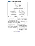
Use one of the power adapters supplied. Connect the
power adapter to the
DC IN 9 VDC
power socket (3)
on the transmitter, then plug the power adapter into a
mains socket.
4.
Now position the transmitter as described in the
section "Optimal positioning of transmitter and
receiver".
5.
Set the
POWER OFF ON
(4) switch on the transmitter
to the ON position. The LED lights to indicate
readiness to operate.
Connecting the transmitter to an audio source
1.
For the exclusive transmission of audio signals you
require a phono to 3.5mm cable (Vivanco accessory,
e.g. 13798 or 13854).
2.
Connect the 3.5mm plug to the
AV
(5) socket of the
transmitter, and the audio phono plugs to the
corresponding output sockets of your audio source.
Make sure the polarity (red/white) is correct.
3.
Use one of the power adapters supplied. Connect the
power adapter to the
DC IN 9 VDC
power socket (3)
on the transmitter, then plug the power adapter into a
mains socket.
4.
Now position the transmitter as described in the
section "Optimal positioning of transmitter and
receiver".
5.
Set the
POWER OFF ON
(4) switch on the transmitter
to the ON position. The LED lights to indicate
readiness to operate.
Connecting the receiver
When transmitting audio/video signals, the receiver can be
connected
direct to a TV or
via an intermediary video recorder. For pure audio
transmission, the receiver can be connected direct to
a hi-fi system.
Direct connection of the receiver to a TV
1.
Set the
power on/off
switch (4) on the receiver to the
OFF position.
2.
Use the 3.5mm-to-scart receiver cable supplied.
Connect the 3.5mm plug to the
AV
socket (5) on the
receiver, and connect the scart plug to the
corresponding scart socket on your TV.
3.
Then connect the power adapter of the receiver.
4.
Now position the receiver as described in the section
"Optimal positioning of transmitter and receiver".
5.
Set the
POWER OFF ON
(4)
switch on the receiver
to the ON position. The LED lights to indicate
readiness to operate.
Connecting the receiver via an intermediary video
recorder
1.
Set the
power on/off
(4) switch on the receiver to the
OFF position.
2.
Use the 3.5mm-to-scart receiver cable supplied.
Connect the 3.5 mm plug to the
AV
socket (5) on the
receiver, and connect the scart plug to the
corresponding scart socket on your video recorder or
DVD recorder.
3.
Then connect the power adapter of the receiver.
4.
Now position the receiver as described in the section
"Optimal positioning of transmitter and receiver".
5.
Set the
POWER OFF ON
(4)
switch on the receiver
to the ON position. The LED lights to indicate
readiness to operate.
The connection between video recorder and TV can be made via
a scart connection between the two devices or using an antenna
cable.
Connecting the receiver for pure audio transmission
1.
Set the
power on/off
(4) switch on the receiver to the
OFF position.
2.
Use a 3.5mm-to-phono cable, e.g. optional Vivanco
13798 or 13854. Connect the 3.5mm plug to the
AV
socket (5) on the receiver, and connect the phono
plugs to the corresponding phono input sockets on
your audio device, e.g. amplifier.
3.
Then connect the power adapter of the receiver.
4.
Now position the receiver as described in the section
"Optimal positioning of transmitter and receiver".
5.
Set the
POWER OFF ON
(4)
switch on the receiver to
the ON position. The LED lights to indicate readiness
to operate.
Transmission of remote control signals from receiver to
transmitter
This audio/video transmitter/receiver set not only allows the
wireless transmission of picture and sound signals, but also
lets you control audio/video sources using the existing
remote controls from another room. The infrared signal for
remote control is captured by the infrared window
IR
(2) of
the receiver, converted into radio signals and then emitted to
the audio/video source as an infrared signal by an infrared
sensor on the transmitter.
1.
Connect the supplied infrared sensor cable to the
IR
socket (7) of the transmitter.
2.
Position the infrared sensor in front of the infrared
window of your audio/video source(s).
3.
To control the device, point the remote control of your
AV source at the IR window (2) of your FM receiver.
As a control, the transmission of IR signals is audible.
Selecting a transmission channel
To ensure optimal signal transmission, 3 different
transmission channels are available. The transmitter and
receiver must always be set to the same transmission
channel, e.g.
CHANNEL 1
, using the slide controls (6) on
the rear of the devices.
– To improve transmission quality, you
should select the best channel. A channel could, for example,
already be occupied by your neighbour.
Optimal positioning of transmitter and receiver
If required, the transmission quality can be optimised by
moving and/or revolving the transmitter and/or receiver
and/or their aerials .
– Sources of interference: radio signals
can be disrupted by electromagnetic radiation, e.g. from
microwave ovens, therefore optimisation as described
above may not help. In such cases, the source of
interference, e.g. the microwave, must be switched off.
Hotline
If you have any questions regarding the
AV TR 3
, please
call the Vivanco Hotline: tel. 01442 246088. Or send an e-
mail to: [email protected]
(D) Sicherheitshinweise
Bitte für ausreichende Belüftung sorgen.
Bitte Geräte nicht bei Temperaturen über 40° C
betreiben
Bitte Geräte vor Feuchtigkeit schützen und nicht im
Freien benutzen.
Die Geräte sollen nur mittels der beigefügten
Netzadapter mit Strom versorgt werden. Der Netzstecker
oder eine Schaltsteckdosenleiste wird zur vollständigen
Stromnetztrennung benötigt. Bitte halten Sie den Zugang zu
Netzsteckdosen
oder
Steckdosenleiste
frei,
und
unterbrechen Sie die Stromverbindung, wenn Sie die
Geräte längere Zeit nicht benötigen.
Die
Geräte
entsprechen
den
einschlägigen
Europäischen
Regeln
für
Produktsicherheit
(LVD),