Using the Power Analyzer
67
user also has to configure the inrush current trigger level (INRUSH
DETECT LEVEL). Inrush & Startup capture is triggered when the
Line Switch is turned on and then waits for an inrush current
detection.
o
Note:
The inrush waveforms (voltage and current signals) are
always captured for a period of approximately 3ms before and
65ms after the trigger event. This data has a time resolution of
nominally 4.1us per point.
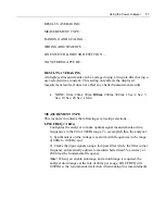
INRUSH DETECT LEVEL
(Shows when INRUSH CURRENT TRIGGER
ENABLE is selected)
This option allows the user to select a user-defined trigger level for
the inrush current or PRESET choices of 100mA, 1A, 10A or 100A.
To set the preset INRUSH DETECTION LEVEL, press the ENTER
key when INRUSH DETECT LEVEL is highlighted. You have the
option to enter your own value by using the F1, F2 keys to scroll the
cursor right and left and the use the up and down arrow keys to
change the character.
To use one of the PRESET values, press the F4 key to enter the
PRESET menu, use the up and down arrow keys to highlight your
selection and press the ENTER key to select your choice. You can
then edit the number or press ENTER again to save and exit out of the
menu.
By pressing the F3 CLEAR key, this will clear your selection.
CAPTURE FILTERED WAVEFORM
(Shows when INRUSH CURRENT
TRIGGER ENABLE is selected)
This option allows the user to configure the waveform capture system in the
analyzer. Waveforms are captured by the analyzer when an “event” occurs on
either the voltage or current signal. This event can be either a peak in the
actual signal or a peak in the “virtual” signal created by removing the
Summary of Contents for Xitron 2801
Page 1: ...USER GUIDE 2801 2802 Advanced Single and Dual Channel Power Analyzers...
Page 2: ...2 2801 2802 Power Analyzer User Guide...
Page 10: ...10 2801 2802 Power Analyzer User Guide...
Page 101: ...Printing Results 101 Figure 66 Configuration Printout...
Page 102: ...102 2801 2802 Power Analyzer User Guide Figure 67 Waveform Channel 1 Real time...
Page 103: ...Printing Results 103 Figure 68 Waveform Channe1 Distortion...
Page 104: ...104 2801 2802 Power Analyzer User Guide Figure 69 History Chart VOLTS ACDC Trends View...
Page 105: ...Printing Results 105 Figure 70 History Chart AMPS PERCENT THD Extents View...
Page 106: ...106 2801 2802 Power Analyzer User Guide Figure 71 Harmonics Listing page 1...
Page 107: ...Printing Results 107 Figure 72 Harmonics Listing page 2...
Page 145: ...Sending Commands and Interrogatives 145...
Page 147: ...Appendix A Physical Specifications 147...

