


12
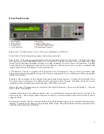
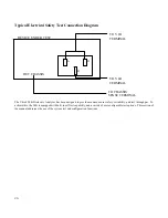
The low resistance measurement is made between the V LO and Chassis Sense terminals. Apply a short to the end of the leads
and press enter. The 944i will measure the lead resistance and store the value in non-volatile memory. Until a new value is stored
the 944i will use this value to offset the lead resistance each time a low ohms test is done. In the event that the lead resistance is
too high or a poor contact is made, the 944i will advise the user to check leads.
Should one elect not to null out the leads or following the null routine the 944i goes directly into the low ohms mode. There is no
"High Voltage Enable" prompt as the low ohms test is conducted with a low voltage constant current source. When measuring
low resistance the reading is displayed in four digit format with a fixed decimal to the right of the most significant digit. The
maximum reading is approximately 8.500 ohms. When the measurement range is exceeded, the display will show four asterisks
(****). In the automatic test mode the Vitrek 944i is a powerful, high volume test system in one compact package. Whether
operating from the front panel or via the GPIB interface, the 944i can quickly execute a wide variety of tests comparing each step
to preset user limits. Test routines can be easily entered, stored, recalled and edited using the 944i's built-in procedure generator.
When the test is completed, hard copy test results are available at the touch of a button, provided the optional IF-4 interface card is
installed. The IF-4 option includes GPIB, RS232, parallel printer port and VICL port.
DC Dielectric Strength Function
The DC Dielectric test in the automatic mode is essentially the same as in direct mode, however, once the parameters for the test
have been set the test is fully automatic. Unlike most testers, all test parameters are fully programmable. The 944i has no rear
panel pots to adjust and no factory set test values.
To begin a new DC Dielectric test, press the VDC key located under the display window. Upon pressing the VDC button, the
following display prompt will appear:
DC DIELECTRIC TEST
DIRECT
AUTOMATIC
This message confirms that the DC function has been selected and offers both operating modes. Use the right cursor arrow to
highlight the Automatic mode and then press enter. The following prompt will appear:
ENTER TEST VOLTAGE
1000
VOLTS
This prompt allows the operator to set the test voltage. The 1000 VDC shown is the default test voltage. To enter another test
voltage, simply press the number keys for the desired value. The range of output for the VDC function may be as low as 100
VDC or as high as 5000 VDC (7000 VDC with option DC-7 or 10,000 VDC with option DC-10). Once the desired test voltage is
displayed, press enter to advance to the next step.
ENTER SLEW RATE
_100
VOLTS/SEC
The slew rate prompt allows the test developer to automatically set the ramp rate so that the output voltage linearly increases up to
the test voltage. The slew rate can be set from 1 volt per second to 2000 volts per second. If 100 v/s is the desired ramp rate press
enter now. If another rate is desired, use the number keys to input a new value and then press enter. The next prompt is as
follows:
ENTER MAX CURRENT
10.0
mA
This value sets the maximum amount of leakage current which the 944i will source without failing the DUT and shutting down the
test. Any current which exceeds this limit will cause the unit to automatically stop the test. The default value is 10.0 mA. Any
value between 1nA and 35mA may be used. To change the value of the current limit, use the number keypad. To change the
units from m (milli) to u (micro) or n (nano), use the up/down cursor arrows. Once the desired maximum current limit is
displayed, press enter. After the maximum current limit is set the next prompt is:
ENTER MIN CURRENT
0.0_
mA
The minimum current limit is provided as a convenience to assure that the load is actually connected. Any current measured
below this limit will cause the unit to automatically stop the test. The default value is 0.0 mA. When the minimum current limit


