background image

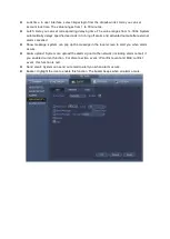
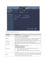
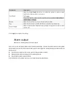
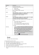
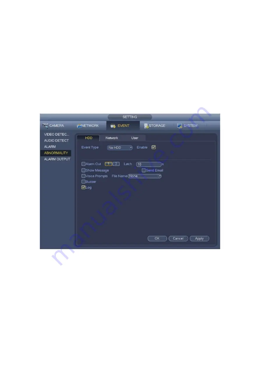
  Lock time: In user interface, select illegal login from the dropdown list. Here you can set 

account lock time. The value ranges from 1 to 30 minutes. 

  Latch: Here you can set corresponding delaying time. The value ranges from 1s-300s. System 

automatically delays specified seconds in turning off alarm and activated output after external 
alarm cancelled. 

  Show message: system can pop up the message in the local screen to alert you when alarm 

occurs.   

  Alarm upload: System can upload the alarm signal to the network (including alarm center) if 

you enabled current function. For disconnection event, IP conflict event and MAC conflict 
event, this function is null. 

  Send email: System can send out email to alert you when alarm occurs.   

  Buzzer: Highlight the icon to enable this function. The buzzer beeps when an alarm occurs. 


Summary of Contents for Optio OPNVR Series

Page 1: ...OPNVR Please read this manual thoroughly before use and keep it handy for future reference User Guide ...

Page 2: ...ister Camera 43 Image 44 Encode 45 Channel Name 49 Remote Upgrade 50 Preview 53 Navigation bar 54 Preview Control Interface 56 Right Click Menu 58 Edit View Sequence 59 Preview Display Effect Setup 62 PTZ Control 65 Playback and Search 71 Search Interface 71 Smart Search Playback 75 Mark Playback 76 Playback Image 78 Splice Playback 78 File List 79 Other Aux Functions 81 Event Manager 81 Video Det...

Page 3: ... FTP 113 Record Control 115 HDD Information 115 HDD Group 116 HDD Detect 117 Account 119 System Info 126 RS232 128 Security 129 Auto Maintain 131 Backup 132 Default 136 Upgrade 137 Logout Shutdown Restart 139 ...

Page 4: ...sistance in installing operating maintaining and troubleshooting this product refer to this document and any other documentation provided If you still have questions please contact Norbain Technical Support and Sales Norbain SD Inspired Easthampstead Road Bracknell Berkshire RG12 1YQ England UK 44 0 118 912 5000 Vista Technical Support 44 0 118 912 5125 Note You should be at the equipment and read...

Page 5: ... Substances RoHS directive 2011 65 EU which means our manufacture processes and products are strictly lead free and without the hazardous substances cited in the directive The crossed out wheeled bin mark symbolizes that within the European Union the product must be collected separately at the product end of life This applies to your product and any peripherals marked with this symbol Do not dispo...

Page 6: ...les and the point where they exit from the apparatus 10 Only use attachments accessories specified by the manufacturer 11 Unplug this apparatus during lightning storms or when unused for long periods of time 12 Refer all servicing to qualified service personnel Servicing is required when the apparatus has been damaged in any way such as power supply cord or plug is damaged liquid has been spilled ...

Page 7: ...ng items Requirement 1 Package Appearance No obvious damage Packing materials No broken or distorted areas that may have been caused by dropping 2 Labels Labels on the device No tears Do not rip up or throw away the labels otherwise the warranty is not valid You will need to provide the serial number of the product should you need to call Norbain customer services 3 Device Appearance No obvious da...

Page 8: ...ctly USB2 0 port Connect to peripheral USB storage device or mouse Rear Panel Icon Port Name Function Network port Connects to Ethernet HDMI High Definition Media Interface High definition audio and video signal output port It transmits uncompressed high definition video and multi channel audio data to the connected display with HDMI port HDMI version is 1 4 USB3 0 port USB3 0 port Connect to mous...

Page 9: ...utputs audio signal to devices such as speakers Bidirectional talk output 1 4 Alarm input port 1 4 GND Alarm input ground port NO1 NO2 Alarm output port 1 2 C1 C2 Power input port Input DC 12V 4A Power switch Power on off button PoE PORTS The 4 8 PoE series product supports total 50W The 16 PoE series product supports total 130W ...

Page 10: ...deleting the previous character Double left click mouse Implement special control operations such as file list to play back the video In multiscreen mode double click one channel to view in full screen Double click current video again to go back to previous multiscreen view Right click mouse Right click in live view window interface the shortcut menu is displayed Exit current menu without saving R...

Page 11: ... it is recommended to refer to the national related standard to use the power source that provides stable voltage with less interference from ripples USP power source is recommended Connect the Device to the monitor Plug in the power cable to the Device Press the power button to turn on the Device The power indicator light is on On the connected monitor the live view screen is displayed by default...

Page 12: ...mended to modify the password regularly Turn on the Device The Device Initialization interface is displayed Configure the password for admin User name The default user name is admin Password confirm password The password ranges from 8 to 32 digitals It can contain letters numbers and special characters excluding The password shall contain at least two of these categories Prompt question In the Pro...

Page 13: ...e high security systems Draw an unlock pattern After this setting is completed the password protection settings interface is displayed Note The pattern that you want to set must cross at least four points If you do not want to configure the unlock pattern click Skip Once you have configured the unlock pattern the system will require the unlock pattern as the default login method ...

Page 14: ...ons Email Input an email address for password reset If the password is forgetten in the future you will need to input the security code received via assigned email to reset the admin password Security question Configure the security questions If the password is forgetten in the future enter the answers to the questions to reset the admin password Click OK to complete the device initialization setu...

Page 15: ...ck pattern login interface If you have not set unlock pattern device displays password interface Note Click Switch User button and NVR goes to general user login interface The default user name is admin Click the user name drop down arrow select a user from the drop down list and then you can log in via a different account Click If you did not set the reserved email address the email entering inte...

Page 16: ......

Page 17: ...a the assigned email The security code sent to the email is only valid for 24 hours Security questions Select security question from the drop down list Device displays security question interface Please input the correct answers here Note You shall configure the security questions before resetting password by answering the questions If you have not configured the questions this method will not be ...

Page 18: ...set password interface Input new password and then confirm The password can be set from 8 to 32 characters and contain at least two types from number letter and special character excluding and Click OK button to complete the setup ...

Page 19: ... basic network setup camera registration P2P and schedule interface Boot up the device and complete the device initialization Device goes to startup wizard Select Auto check for updates device automatically checks if there are new updates Note If you select the Auto check for updates check box the system will notify you automatically when updates are available ...

Page 20: ...n view in the preview interface The value ranges from 5 to 60 minutes Auto logout Here you can set auto logout interval Value ranges from 0 to 60 minutes Monitor channels when logout Here you can set the channels you want to view when your account has logged out Click the button and then cancel the channel name box you need to login to view the corresponding video The channel window displays in pr...

Page 21: ...neral Date Time System time Set system time Date format There are three types YYYYY MM DD MM DD YYYYY DD MM YYYY Date separator There are three denotations to separate date dot beeline and solidus DST Enable the Daylight Saving Time function Click Week or click Date Time format There are two types 24 hour mode or 12 hour mode NTP It is to set NTP server port and interval ...

Page 22: ...o not modify this setting unless there is a must Before your time modification please stop record operation first Holiday Main menu Setting System General Holiday You can configure the device basic settings time settings and holiday settings ...

Page 23: ......

Page 24: ...work Settings Main menu Setting Network TCP IP Set device IP address DNS Domain Name System information Preparation Make sure the device has properly connected to the network Click device display edit interface ...

Page 25: ... default gateway must be in the same network range DHCP Enable the DHCP function to get the DNS address from router MTU It is to set MTU value of the network adapter The value ranges from 1280 7200 bytes The default setup is 1500 bytes IP Version There are two options IPv4 and IPv6 Right now system supports these two IP address format and you can access via them Preferred DNS server DNS server IP ...

Page 26: ...edure Scan the QR code download mobile app and then register an account Connect the NVR device to the Internet otherwise P2P can not run properly If system displays Online in the Status box P2P registration is successful EasyViewer Mobile APP Operation Scan the QR code to download and install the mobile App Select Camera and enter the main interface Register device in the mobile App Click and sele...

Page 27: ...er the P2P interface Click the QR code icon behind the SN to enter the QR code scan interface Scan the device label or scan the SN QR code When the scan is successful the device SN will be displayed in the SN item Enter name and password After device registraion on mobile App click Start Preview and you can see the monitor screen ...

Page 28: ...y adding the IP address Channel It is the device channel number Status Red circle means the channel has no video green circle means the channel has video IP address It is to display network camera IP address Add Delete Click to delete the device click to add the device to the NVR ...

Page 29: ...s 554 HTTP port Input HTTP port of the remote device The default setup is 80 TCP port Input TCP port of the remote device The default setup is 37777 User name password The user name and password to login the remote device Channel No Input channel number or click the connect button to allocate the channel Remote channel No After getting the remote device channel number click Setup to select a chann...

Page 30: ...Note Click to change the remote device information Click to delete remote device ...

Page 31: ...t to record continuously by default You can set customized record period and record type Channel Select the channel to configure schedule Select icon of several dates all checked items can be edited or together Link icon Click it to delete a record type from one period or multiple if linked Record Type Please check the box to select corresponding record type There are 4 types Regular MD motion det...

Page 32: ...em can pre record the video before the event occurs The value ranges from 1 30 seconds Period setup Click button after one date or a holiday There are 4 record types regular motion detection MD Alarm MD alarm Note When the record type is MD motion detect alarm MD Alarm please enable the channel record function when corresponding alarm occurs ...

Page 33: ... you can set the record period for the holiday Schedule Snapshot Main menu Setting Storage Schedule Snapshot You can configure the storage schedule for the snapshot such as channels to take snapshot alarm settings and the armed period ...

Page 34: ...lan can become activated Record Control Main menu Setting Storage Record There are two ways to access the record menu Right click mouse and then select Manual Record In the main menu from Setting Storage Record After setting record schedule and snapshot schedule function please enable auto record and auto snapshot function so that the device can automatically record and snapshot System supports ma...

Page 35: ...cords according to the record schedule Off Current channel stops recording All Check All button after the corresponding status to enable disable all channel schedule manual record or enable disable all channels to stop record Snapshot Enable disable schedule snapshot function Record Info Main menu Info System Record After the system has video recordings go to the record info interface to view devi...

Page 36: ... the storage Change camera IP address Main menu Setting Camera Registration Check the box before the camera name and then click Change IP or click the before the camera name Enter change IP interface Note Check the box before several cameras change the IP addresses of several cameras at the same time ...

Page 37: ...hange several devices IP addresses at the same time please input incremental value When changing IP address buy batch device automatically skips the conflicted IP and begin the allocation according to the incremental value Input remote device user name and password Click OK button to save settings Note When changing IP addresses of several devices at the same time make sure the camera user names a...

Page 38: ...ccessful Click OK button to exit Note Backup encryption is enabled by default when exporting files The file information includes IP address port remote channel number manufacturer user name and password When you enable backup encryption the extension name of the exported file is backup All the other softwares cannot open the file to edit except the NVR device When you disable backup encryption the...

Page 39: ... to remind you You have two options Important You can edit the exported CVS file Do not change the file format otherwise it may result in import failure Does not support customized protocol import and export The import and export device shall have the same language format Remote Device Initialization Main menu Setting Camera Registration Remote device initialization can change remote device login ...

Page 40: ...itialize the camera Enter Registration interface Click Device Search and then click Uninitialized Device displays camera s to be initialized Select a camera to be initialized and then click Initialize Device displays password setup interface Note If you want to use current device password and email information the remote device automatically uses NVR admin account information login password and em...

Page 41: ...e recommend the strong password In order to guarantee device security please keep the admin login password in a safe place after the device has been initialized it is recommended to modify the password regularly Click Next button Enter input email interface Set email information Email Input an email address for reset password purpose Note Click Next or Skip if you do not want to input email inform...

Page 42: ...IP address subnet mask default gateway and incremental value Note To change several devices IP addresses at the same time please input incremental value If there is an IP conflict when changing the static IP address an IP conflict dialog box pops up If changing a batch of IP addresses device automatically skips the conflicting IP and begins the allocation according to the incremental value Click N...

Page 43: ...Menu to Register Camera If you have not registered a remote device to a channel please go to the preview interface to add On the preview interface Move your mouse to the center there is an icon Click device pops up interface to add network camera ...

Page 44: ...ntrast Adjusts the image contrast The bigger the value the more obvious the contrast between the light area and dark area will become The value ranges from 0 to 100 The default value is 50 The recommended range is between 40 and 60 Auto Iris Check the box to enable this function This function is on by default Mirror Switch the video to mirror mode This function is disabled by default Flip Rotate t...

Page 45: ...is to set device bit stream type Main stream there are three options regular motion detect alarm The sub stream supports regular bit streams only The active control frame function ACF can record different frame rates For example you can use high frame rate to record important events record scheduled event in lower frame rate Set different frame rates for different record events Compression Video e...

Page 46: ...her the image will become Frame rate changes along with the resolution Bit rate type In the Bit Rate list select a value or enter a customized value to change the image quality The bigger the value is the better the image will become Video audio You can enable or disable the video audio The main stream is enabled by default After enable the audio function the record file is composite file consisti...

Page 47: ... monitor Cover area has two types Preview and Monitor Preview means the privacy mask zone cannot be viewed by user when system is in preview status Monitor means the privacy mask zone cannot be view by the user when system is in monitor status Time display You can select system displays time or not when in playback Please click set button and then drag the title to the corresponding position in th...

Page 48: ...des regular and trigger If you set regular mode you need to set snapshot frequency If you set trigger snapshot you need to set snapshot activation operation Image size Here you can set snapshot picture size Image quality Here you can set snapshot quality The value ranges from 1 to 6 Interval Set timing schedule snapshot interval ...

Page 49: ...Channel Name Main menu Setting Camera Cam name Modify channel name Supports maximum of 63 character Please note you can only modify the channel name of the connected network camera ...

Page 50: ...grade Main menu Setting Camera Registration Upgrade Upgrade the connected network camera firmware It includes online upgrade and file upgrade From main menu setting camera remote the interface is shown as below ...

Page 51: ...ersion on the internet Select a remote device that requires a new version and then click online upgrade After successful operation system pops up upgrade successful dialogue box File upgrade Select a channel and then click File upgrade Select upgrade file on the pop up interface Select the upgrade file and then click OK button After successful operation system pops up upgrade successful dialogue b...

Page 52: ... tampering alarm IP camera status Front end does not support Front end supports There is alarm event from current front end Connection status Connection succeeded Connection failed Refresh Click it to get latest front end channel status Firmware Main menu Setting Camera Registration Firmware It is to view channel IP address manufacturer type system version SN video input audio input external alarm...

Page 53: ...isplays in multiple channel mode If you want to change system date and time you can refer to general settings Main Menu Setting System General If you want to modify the channel name please refer to the display settings Main Menu Camera CAM name ...

Page 54: ...use in the channel 1 and then drag to channel 2 release mouse you can switch channel 1 and channel 2 positions Use mouse scroll to control digital zoom You can use the mouse to zoom in and out of the image Navigation bar On the preview interface left click mouse you can view the navigation bar Note Go to the Main menu Setting System General to enable navigation bar function disabled by default Mai...

Page 55: ...lick system goes to search interface Alarm Status Click to check alarm status interface It is to view device status and channel status Channel Info Click for the channel information interface To view information of the corresponding channel Registration Click system goes to the registration interface ...

Page 56: ...DD information USB Manager Click system goes to the USB Manager interface View USB information backup and update Preview Control Interface Move you mouse to the top center of the video of the current channel you can see system pops up the preview control interface If your mouse stays in this area for more than 6 seconds and has no operation the control bar automatically hides ...

Page 57: ... and go back to the original interface Manual record function It is to back up the video of current channel to a USB device System cannot backup the video of multiple channel at the same time Click button system begins recording Click it again system stops recoridng You can find the record file on the USB device Manual Snapshot Click to snapshot 1 5 times The snapshot file is saved on the USB devi...

Page 58: ...itable for video wall surveillance storage etc S Sub stream Definition is low but occupies small network bandwidth It is suitable for general surveillance remote connection etc Right Click Menu After you logged into the device right click mouse the short cut menu will be displayed Window split mode You can select window amount and then select channels Sequence Change channel display sequence on th...

Page 59: ...it View Sequence On the preview interface right click mouse and then click Edit view Enter edit view interface Note Enter edit view interface device automatically switches to the max split amount mode The channel list on the edit view interface displays the added camera channel number and channel name means camera is online means camera is offline In case the channel amount has exceeded the device...

Page 60: ...the edit view interface drag the channel to the desired window or drag on the preview window to switch the position Check the channel number at the bottom right corner to view the current channel sequence ...

Page 61: ...ve current channel sequence After changing the channel sequence click Cancel button or right click mouse device pops up the dialogue box Click OK to save current settings Click Cancel to exit without saving the settings ...

Page 62: ...ult value is 50 and the recommended value ranges from 40 to 60 Brightness Adjust the image brightness The value ranges from 0 to 100 The default value is 50 The bigger the value is the brighter the image will become The recommended range is between 40 and 60 Contrast Adjust the image contrast The bigger the value is the more obvious the contrast between the light area and dark area will become You...

Page 63: ...the video brightness if the value is high But the video noise may become too clear Color mode In the Color Mode list you can select Standard Soft Bright Colorful Bank Customized 1 Customized 2 Customized 3 and Customized 4 The sharpness hue brightness contrast and saturation will adjust automatically according to the selected color mode Display Main Menu Setting System Display Display These settin...

Page 64: ...ale Check the box here to select a corresponding channel it can restore video original scale Click OK button to save current setup Preview Tour Parameters Main Menu Setting System Display Tour Here you can set tour parameter Enable tour Check the box to enable tour function The general tour supports all types of window split mode Interval Input proper interval value here The value ranges from 1 12...

Page 65: ...Tips On the navigation bar click to enable disable tour PTZ Control Right click mouse Please note you can only go to the PTZ control interface when you are in single window display mode ...

Page 66: ...ng camera in eight directions adjusting zoom focus and iris settings and quick positioning Speed Controls the movement speed The bigger the value is the faster the movement will be You can click and of the zoom focus and iris to zoom in out definition and brightness The PTZ rotation supports eight directions In the middle of the eight direction arrows there is a 3D intelligent positioning key ...

Page 67: ...tion Shortcut key Zoom Near Far Focus Near Far Iris close Open Click to open the expanded menu you can set preset tour pattern scan etc Please note the above interface may vary due to different protocols The button is grey and cannot be selected once the current function is null Right click mouse to go back Icon Function Icon Function Preset Flip Tour Reset Pattern Aux Scan Aux on off button Rotat...

Page 68: ... Click Setting to complete the preset settings Tour Setup Click the Tour tab The Tour tab is displayed In the Patrol No box enter the value for the tour route In the Preset box enter the preset value Click Add Preset A preset will be added for this tour Tips Repeat the above steps to add more presets to the tour Click Del preset button to remove it from the tour Please note some protocols do not s...

Page 69: ... perform the directions operations You can also go to the PTZ Control Panel to perform the operations of adjusting zoom focus iris and directions On the PTZ interface click End to complete the settings Scan Setup Click the Border tab The Border interface is displayed Click the direction arrows to position the left and right borders ...

Page 70: ...ue and then click to call a pattern Click to stop calling Call Tour Input tour value and then click to call a tour Click to stop calling Call Scan Input Scan value and then click to call a tour Click to stop calling Auto Pan Click to enable the camera to Auto Pan System supports preset tour pattern scan rotate light and etc function ...

Page 71: ...rface In the Direct Aux list select the option that corresponds to the applied protocol In the Aux Num box enter the number that corresponds to the AUX switch on the decoder Playback and Search Playback Controls Search Interface Main menu Search ...

Page 72: ...le under the date Click the date that you want to search the time bar displays the corresponding recordings Time Bar Display the type and time period of the selected recorded video In the 4 channel layout four time bars are displayed in the other view layouts only one time bar is displayed Click on the colored area to start playback from a certain time Use the mouse scroll wheel to zoom in to the ...

Page 73: ...t playback click to slow down the speed of fast playback Fast Playback During playing back click to set the speed of fast playback as FastX2 FastX4 FastX8 or FastX16 During slow playback click to speed up slow playback Smart search not avaiable in all models Adjust volume of playback In the full screen mode click to take a snapshot and save to a USB storage device Add Mark for the recorded view Ti...

Page 74: ...gital zoom When the system is in full screen playback mode left click the mouse Drag the mouse to select a section and then left click mouse to digital zoom Right click mouse to exit Clip This function allows you to clip some footages to a new file and then save to the USB device Please follow the steps listed below Click to start playback from the beginning Click on the time bar to select the sta...

Page 75: ...t want to backup the file uncheck the box Click Backup to begin the process Smart Search Playback Main menu Setting Event Video detect Motion detect Whilst playing back video motion detection you can analyze a certain area to find when a specific event occurred The system will display the motion events within this area Not all models support this function ...

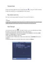
Page 76: ...e screen and then you can start using smart search function Drag the pointer to select the searching area Click The screen starts playing back the motion splices of recorded video for the selected area Click to exit the playback Mark Playback When you are playback record you can mark the record when there is important information After playback you can use time or the mark key words to search corr...

Page 77: ...ybacks from the previous X seconds when there is such as kind of record Mark Manager Click the mark manager button on the Search interface you can go to Mark Manager interface By default it manages all the marked videos of the selected channel To search the marked video select channel number from the Channel list enter time in Start Time box and End Time box and then click Search All the marked vi...

Page 78: ...rom the first file in the list Playback Image You can search and review recorded snapshots Select Main Menu VIDEO the video search interface is displayed In the Search Type list select PIC In the Channel list select a channel number In the Calendar area select a date Click The system starts playing snapshots according to the configured intervals Splice Playback Select Main Menu VIDEO the video sea...

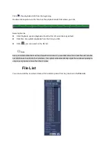
Page 79: ...m playbacks from the time you click Click you can select on the file list Note Every recorded video file must be at least five minutes If a recorded video file is less than 20 minutes but still choose to split into four windows the system will automatically adjust the windows quantity to ensure every splice is more than five minutes File List You can view all the recorded videos within a certain p...

Page 80: ... time to search the file that you want to view In the File List area 128 files can be displayed File type R indicates general recorded video A indicates recorded video with external alarms M indicates recorded video with motion detection events Lock or Unlock File Select the video you want to lock from the File List interface and then click The locked video will not be overwritten Note The recorde...

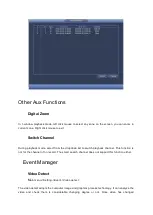
Page 81: ...t from the dropdown list to switch playback channel This function is not for the channel of no record The smart search channel does not support this function either Event Manager Video Detect Main menu Setting Event Video detect The video detect adopts the computer image and graphics process technology It can analyze the video and check there is considerable changing degree or not Once video has c...

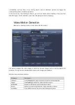
Page 82: ...otion detect The system analyzes the video images to detect an obvious change such as moving objects and blurriness The system can activate alarms when such changes are detected Detection menu is shown as below Parameter Description Channel In the Channel list select a channel to set the motion detection Region Click Setting to define the motion detection region Enable MD Enable or disable the mot...

Page 83: ... s starts recording after an alarm event occurs The recording for motion detection and auto recording function must be enabled PTZ Click Setting to display the PTZ interface Enable PTZ activation function For each PTZ camera select the preset that you want to be called when an alarm event occurs Post Record Set a length of time for the Device to delay turning off recording after the alarm is cance...

Page 84: ...ault setting Click Copy in the Copy dialog box select the additional channel s that you want to copy the motion detection settings to and then click Apply Click Test to test the settings Setting the Motion Detection Region Next to Region click Setting The region setting screen is displayed Move mouse pointer to top middle of the interface screen The region setting interface is displayed ...

Page 85: ......

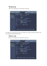
Page 86: ...ent Video detect Tampering If the camera lens is covered or the video is over exposed due to sunlight To avoid such situations you can configure the tampering alarm settings Video Loss Main menu Setting Event Video detect Video loss ...

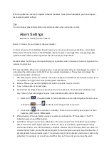
Page 87: ...esponding alarm operations Enable Please you need to highlight this button to enable current function Type normal open or normal close Period Click set button There are two ways for you to set periods There are max 6 periods in one day There are four record types regular motion detection MD Alarm MD alarm Select icon of several dates all checked items can be edited together Now the icon is shown a...

Page 88: ...mage as the attachment Please go to the Main Menu Setting Network Email interface to set Record channel you can select proper channel to record alarm video Multiple choices You need to set alarm record mode as Schedule in Record interface Main Menu Advanced Record Please note the manual record has the highest priority System record all the time no matter there is an alarm or not if you select Manu...

Page 89: ...em event the system activates an alarm in accordance with these settings Disk Disk error no disk no space Network Disconnection IP conflict MAC conflict User Unauthorised login Alarm output Select alarm activation output port Less than System can alarm you when the HDD space is less than the threshold you set here For HDD no space type only Attempts In user interface select illegal login from the ...

Page 90: ...ctivated output after external alarm cancelled Show message system can pop up the message in the local screen to alert you when alarm occurs Alarm upload System can upload the alarm signal to the network including alarm center if you enabled current function For disconnection event IP conflict event and MAC conflict event this function is null Send email System can send out email to alert you when...

Page 91: ... after your entries exceed the maximum number Lock Time Set how long the account is locked for The value ranges from 1 minute to 60 minutes Alarm Out Click Setting to display setting interface not supported by all models General Alarm Enable alarm activation through the alarm devices connected to the selected output port External Alarm Enable alarm activation through the connected alarm box Latch ...

Page 92: ...enable audio broadcast voice prompts in response to a user account alarm event Click Apply to complete the settings Alarm output Main menu Setting Event Alarm output Here is for you to set proper alarm output Auto manual stop Connect the alarm device to the system alarm output port and set the mode as auto system can trigger the corresponding operations when an alarm occurs Auto Once an alarm even...

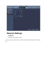
Page 93: ...Network Settings TCP IP Main menu Setup Network TCP IP You can configure the settings for the recorder such as IP address DNS according to the networking plan ...

Page 94: ...he value according to your actual situation UDP Port The default value setting is 37778 You can enter the value according to your actual situation HTTP Port The default value setting is 80 You can enter the value according to your actual situation RTSP Port The default value setting is 554 You can enter the value according to your actual situation HTTPS Enable Enable HTTPS HTTPS Port HTTPS communi...

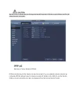
Page 95: ...ict PPPoE Main menu Setup Network PPPoE PPPoE is another way for the Device to access the network You can establish network connection by configuring PPPoE settings to give the Device a dynamic IP address in the WAN To use this function firstly you need to obtain the user name and password from the Internet Service Provider ...

Page 96: ...access the Device by using the domain Preparation If using Quick DDNS type domain registration is not needed If using other DDNS type you need to login to the DDNS website to register the user name password and domain name After you register the device and log in the DDNS website you can view all connected device information of the current user Select Main Menu NETWORK DDNS The DDNS interface is d...

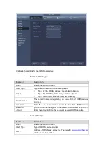
Page 97: ...Domain Name The domain name for registering on the website of DDNS service provider User Name Enter the user name and password obtained from DDNS service provider You need to register on the website of DDNS service provider Password Interval Enter the amount of time that you want between DDNS updates Quick DDNS type Parameter Description Enable Enable the DDNS function DDNS Type Type of DDNS servi...

Page 98: ... Click Apply to complete the settings Enter the domain name in the browser on your PC and then press Enter If the web interface of the Device is displayed the configuration is successful If not the configuration is failed UPnP Main menu Setup Network UPnP You can map the relationship between the LAN and the WAN to access the Device on the LAN through the IP address on the WAN Preparation Login the...

Page 99: ......

Page 100: ...mapped on the router To avoid the conflict when setting the external port try to use the ports from 1024 through 5000 and avoid popular ports from 1 through 255 and system ports from 256 through 1023 When establishing a mapping relationship please ensure the mapping ports are not occupied or limited The internal and external ports of TCP and UDP must be the same and cannot be modified Click to mod...

Page 101: ...end out the email regularly as you set here Click the Test button you can see the corresponding dialogue box to see the email connection is OK or not Please note system will not send out the email immediately when the alarm occurs When the alarm motion detection or the abnormity event activates the email system sends out the email according to the interval you specified here This function is very ...

Page 102: ...MP port number Read Community Write Community The read community write community string supported by the program Trap Address Enter the IP address of the PC installed with MG SOFT MIB Browser It is the destination address to receive trap information from the device Trap Port The destination port to receive trap information from the device Read Only User Enter the read only username to access the N...

Page 103: ...er 4 Enter the PC IP address into MG SOFT MIB Browser and select the version to search 5 Expand the tree list in MG SOFT MIB Browser to view the device configuration information such as channel number and program version Multicast Main menu Setup Network Multicast You can use the multicast function to group the communication and transmit to a group of destination computers simultaneously Select th...

Page 104: ...the setting After configuring the multicast you can log in Web with multicast On the web login dialog box in the Type list select MULTICAST The web will automatically obtain the multicast IP address and join Then you can view the video through multicast function Multicast can be selected via Type dropdown Auto register Main menu Setup Network Register You can register the Device into the specified...

Page 105: ...y the server and used for the Device Click Apply to complete the settings P2P Main menu Setup Network P2P You can manage the devices by using P2P technology to download the application and register the devices You can add the reordering device into your EasyViewer mobile phone APP without registering DDNS or setting port forward by following the below procedure After you have configured the networ...

Page 106: ...d the Device SN into the platform Then you can access and manage the device in the WAN You can also enter the QR code of Cell Phone Client and Device SN by clicking on the top right of the interfaces after you have entered the Main Menu SWITCH Main menu Setup Network Switch When connect a network camera to the PoE port of the NVR NVR can automatically allocate the IP address according to the speci...

Page 107: ...small PoE icon at the top left corner Go to the Register interface to view the connected device list you can see the PoE channel number PoE port information and etc Click IP search to display or refresh the information Remove camera from the PoE port After remove the camera network cable from the PoE port the channel displays Cannot find the network host On the registration interface the IP addres...

Page 108: ...n check the evaluation for average delay packet loss and network status Capturing Packet and Backing up Packet capture means the operations such as capturing resending and editing data that are sent and received during network transmission When there is network abnormality you can perform packet capturing and backup to a USB storage device This data can technical support in analyzing the network c...

Page 109: ... click to delete the needless files Click New Folder to create a new folder in the USB storage device 3 Click Apply to save the route selection settings The Test interface is displayed again Click to start packet capturing and backing up Only the data packet of one LAN can be captured at one time After capturing starts you can exit the Test interface to perform other operations such as web login a...

Page 110: ...ation such as type status total capacity record time and etc The operation includes format resume from error change HDD property Read write Read only Here you can also set alarm and HDD storage position Basic Main menu Setup Storage Basic ...

Page 111: ...ing Select Overwrite to overwrite the recorded video files always from the earliest time Pack Mode Specify the record file length The max is 120 mins Auto Delete Old Files Configure whether the device deletes old recordings select Customized to configure the time length for how long you want to keep the old files or select Never to keep for as long as you have hard disk space Schedule Main Menu ST...

Page 112: ... of current HDD such as device name HDD type status total space and free space and serial number of the HDD port Configuring the settings for the HDD manager HDD type setting In the Type list select Read Write Read Only or Redundant and then click Apply To save the settings HDD format Select the HDD that you want to format click Format in the pop up message click OK to start formatting and then fo...

Page 113: ... Purchase or download a FTP server and install it on your PC For the created FTP user you need to set the write permission otherwise the upload of recorded videos and snapshots will fail Configuration Steps Select Main Menu STORAGE FTP The FTP interface is displayed Configure the settings for the FTP settings parameters ...

Page 114: ...tered length is 0 the whole recorded video will be uploaded Image Upload Interval Sec If this interval is longer than snapshot interval the system takes the recent snapshot to upload For example the interval is 5 seconds and snapshot interval is 2 seconds per snapshot the system uploads the recent snapshot every 5 seconds If this interval is shorter than snapshot interval the system uploads the sn...

Page 115: ...M A R T information Parameter Description No Indicates the number of the currently connected HDD The asterisk means the current working HDD Device Name Indicates the name of HDD Physical Position Indicates the installation position of HDD Type Indicates HDD type Total Space Indicates the total capacity of HDD Free Space Indicates the usable capacity of HDD Status Indicates the status of the HDD to...

Page 116: ...is recording the video HDD Group It is to set HDD group and HDD group setup for main stream sub stream and snapshot operation Caution When you are setting HDD group please set a HDD for each channel otherwise NVR cannot save current setup HDD Here you can view the HDD amount the device can support Group It lists the HDD Group number of current hard disk Please select the correspond group from the ...

Page 117: ...ly complete the HDD scan If you want to use this function please make sure the HDD is in use now If the HDD is removed from other device please make sure the write data once was full after it installed on current device Global detect adopts Windows mode to scan It may take a long time and may affect the HDD that is recording Manual Detect Main menu Setting Storage HDD Detect Manual Detect Detect R...

Page 118: ...Click View you can see the detailed information such as detect result backup and S M A R T ...

Page 119: ...letters numbers and _ The default user amount is 64 and the default group amount is 20 System account adopts two level management group and user The user authorities shall be smaller than group authorities The admin user authorities are set by default For group or user management there are two levels admin and user The user name shall be unique and one user shall only belong to one group Add User ...

Page 120: ...Input the user name password select the group it belongs to from the dropdown list Then you can check the corresponding rights for current user Modify user ...

Page 121: ...g System Account User Click you can go to the following interface to change user information For admin user you can change the email enable disable unlock pattern change password prompt question set security questions ...

Page 122: ...ick Delete button to reset security questions and answers again Change Password Check the Modify password box you can change password Please input old password and then input new password twice to confirm Note Password confirm password The password ranges from 8 to 32 digitals It can contain letters numbers and special characters excluding The password shall contain at least two categories Usually...

Page 123: ...Step 1 Click add group button Enter Add group the interface Step 2 Input group name and then input some memo information if necessary Check the box to select authorities ...

Page 124: ...ou can reset admin account password Input correct security answers and then click Delete button at the bottom of the interface you can reset security questions and answers ONVIF User Main menu Setting System Account ONVIF When the camera from the third party is connected with the NVRvia the ONVIF user please use the verified ONVIF account to connect to the DVR Here you can add delete modify user N...

Page 125: ...ted after you initialize the DVR Click Add User button Enter Add User interface Set user name password and then select group from the dropdown list Click Save to complete setup Note Click to change user information click to delete current user ...

Page 126: ...ed to your NVR You can click button to disconnect or block one user if you have proper system right System detects there is any newly added or deleted user in each five seconds and refresh the list automatically System Info Version Main menu Info System version BPS Main menu Info System BPS ...

Page 127: ...Here is for you to view current video bit rate kb s and resolution Event Information Alarm Status Main menu Setting Event Alarm Status ...

Page 128: ...eyboard Transparent COM adapter is to connect to the PC to transfer data directly Protocol COM is for card overlay function Network keyboard is for you to use the special keyboard to control the device PTZ matrix is to connect to the peripheral matrix control Note Different series products support different RS232 functions Baud rate You can select proper baud rate Data bit You can select proper da...

Page 129: ...upports valid address of IPv4 and IPv6 After you enabled trusted sites function only the IP listed below can access current NVR If you enable blocked sites function the following listed IP addresses cannot access current NVR Enable Highlight the box here you can check the trusted site function and blocked sites function You cannot see these two modes if the Enable button is grey Type You can selec...

Page 130: ...ewly added IP address e System only checks start address if you add IP address System check start address and end address if you add IP section and the end address shall be larger than the start address f System may check newly added IP address exists or not System does not add if input IP address does not exist Delete Click it to remove specified item Edit Click it to edit start address and end a...

Page 131: ...be push to the EasyViewer mobile app CGI Enabled by default The device can be connected via this protocol when enabled ONVIF Enabled by default The device can be connected via this protocol when enabled Audio VideoEncryption The stream transmission is encrypted when this function is enabled The associated device or software shall support decryption Auto Maintain Here you can set auto reboot time a...

Page 132: ...ect proper setup from dropdown list After all the setups please click save button system goes back to the previous menu Backup Main menu Backup a Connect USB burner USB device or portable HDD and etc to the device ...

Page 133: ...nd remained d System only backup files with a before channel name You can use Fn or cancel button to delete after file serial number e Click backup button you can backup selected files There is a process bar for you reference f When the system completes backup you can see a dialogue box prompting successful backup g Click backup button system begins burning At the same time the backup button becom...

Page 134: ...lder and etc function Export Please connect the peripheral device first and then go to the following interface Click Export button you can see there is a corresponding Config_Time folder Double click the folder you can view some backup files Import Here you can import the configuration files from the peripheral device to current device You need to select a folder first You can see a dialogue box a...

Page 135: ...ce Backup Log Main menu Info Log a Select log type and then set start time end time click Search button you can see log time and event information Click to view detailed log information b Select log items you want to save and then click backup button you can select a folder to save them Click Start to backup and you can see the corresponding dialogue box after the process is finish USB Device Auto...

Page 136: ...ase think twice before you begin the operation You can restore factory default setup to fix some problems when the device is running slowly Configuration error occurred Check an item you want to restore default setup or check the All to select all items Click OK or apply button system pops up a dialogue box Click OK to restore ...

Page 137: ... Setting System Update Step 1 Insert USB device that contain the upgrade file Step 2 Click Start button and then select the bin file Step 3 You can see the corresponding dialogue box after the update process is complete ...

Page 138: ... the upgrade process make sure that the network connection and power supply are normal Step 1 Version check Auto check Select the Auto check for updates check box and click Save Note System enables this function by default Manual check Click Manual Check System starts to search new version and displays the result after the check is completed When system displays that it is the latest version the c...

Page 139: ... img and update img The USB device shall connected to the USB port at the front panel Otherwise NVR cannot properly detect the file or upgrade Logout Shutdown Restart Main menu Operation Shutdown Shutdown System shuts down and turns off power Logout Log out menu You need to input password when you login the next time Restart reboot device If you shut down the device there is a process bar for your...

Reviews: