SECTION 4: INSTALLATION REFERENCE
44
EPI800 Manual.doc
EPI 800 MANUAL
2001 Vision Microsystems Inc.
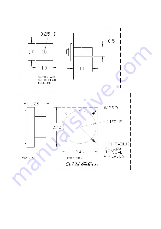
FIGURE 1: EPI 800 IND. & SWITCH MOUNTING
Page 1: ...ns heirs and employees free and harmless from all loss liability or damage resulting from claims brought by any reason of alleged failure or defect of any parts supplied by VISION MICROSYSTEMS INCORPORATED VISION MICROSYSTEMS INCORPORATED has made every effort to document this product accurately and completely However VISION MICROSYSTEMS INCORPORATED assumes no liability for errors or for damages ...
Page 2: ...this product 3 Equipment or parts which have been subjected to misuse abuse accident alteration neglect unauthorized repair or installation are not covered by this warranty Vision Microsystems Incorporated shall have the right of final determination as to the existence and causes of defect 4 When items are replaced or repaired the warranty shall continue in effect for the remainder of the warranty...
Page 3: ......
Page 4: ......
Page 5: ...CH INSTALLATION 3 1 4 RPM TRANSDUCER INSTALLATION 4 1 5 MANIFOLD PRES TRANSDUCER INST 5 1 6 OIL TEMPERATURE TRANSDUCER INST 6 1 7 OIL PRESSURE TRANSDUCER INST 6 1 8 FUEL FLOW TRANSDUCER INST 7 1 9 FUEL PRES TRANSDUCER INST 8 1 10 CYLINDER HEAD TEMP PROBE INST 9 1 11 EXHAUST GAS TEMP PROBE INST 10 1 12 VOLTAGE SENSE WIRE INST 11 1 13 AMP TRANSDUCER INST 11 1 14 O A T TRANSDUCER INST 12 1 15 C A T T...
Page 6: ...COMPUTER NORMAL OPERATION MODES 26 2 9 CYLINDER ANALYZER SYSTEM OPERATION 27 2 10 LEANING YOUR ENGINE 28 2 11 ELECTRICAL MONITORING SYSTEM OPERATION 29 2 12 AIR TEMPERATURE SYSTEM OPERATION 30 2 13 CHRONOMETER SYSTEM OPERATION 31 2 14 INITIAL CHRONOMETER SET UP 32 2 15 CHRONOMETER MODES 34 2 16 IO INTERFACE BOARD OPERATION 36 2 17 FUEL LEVEL SYSTEM OPERATION 37 2 18 FUEL LEVEL SYSTEM CALIBRATION 3...
Page 7: ...8 Amps Transducer Orientation 52 FIGURE 9 Display Cable Shield Installation 62 APPENDIX A Transducer Connector Wiring Techniques 53 APPENDIX B DPU P1 Connector Harness Fabrication 55 APPENDIX C DPU P2 Connector Harness Fabrication 58 APPENDIX D Display Cable Fabrication 60 APPENDIX E IO Interface Board J2 Wiring 64 APPENDIX F System Block Diagram 65 APPENDIX G Recommended Tools 66 APPENDIX H Fuel ...
Page 8: ......
Page 9: ...cers connect to the DPU harness connectors Refer to APPENDIX B and APPENDIX C for DPU wiring connections NOTE On P1 all cable shield wires are to be connected to the system shield wire which is then connected to P1 1 The braided shield wire at the transducer end should be snipped off 1 1 3 Wiring of DPU Display Cable Harness The display cable is simply fabricated by positioning the connectors on t...
Page 10: ...ordingly Test your new screw lengths by finger tightening them into the panel and indicator The screws should tighten against the panel only and should not bottom out in the indicator Be careful not to cross thread the screws or the indicator bezel will be permanently damaged The cut out and mounting space requirement information is provided in FIGURE 1 EPI 800 IND SWITCH MOUNTING If you are uncom...
Page 11: ...ion If you have accidentally moved the ring it should be placed back onto the switch with the tab inserted into the hole between switch position numbers 9 and 10 This tab acts as a stop to only allow switch positions 1 through 9 to be selected STEP 3 Insert the switch assembly switch optional position locking ring and lock washer through the back of the panel Place the nut on the switch and finger...
Page 12: ...ug and screw the RPM transducer in its place then tighten Connect to the DPU Harness as shown in APPENDIX B DPU P1 Connector Harness Fabrication You may connect it either using the supplied terminals or with an equivalent or better method ELECTRONIC IGNITION If you are connecting to an Electronic Ignition that does not use magnetos the RPM transducer is not installed Instead connect the manufactur...
Page 13: ...on and thread requirements Connect to the DPU harness as shown in APPENDIX B DPU P1 Connector Harness Fabrication using the supplied terminals IMPORTANT NOTES DO NOT remove or drill the snubber inner silver filter DO NOT modify connect to or break off the small black plastic hose nipples on the sensor body DO NOT mount the transducer near extremely hot areas such as heater ducts etc DO NOT mount t...
Page 14: ...an equivalent or better method 1 7 OIL PRESSURE TRANSDUCER INST Using the provided Adell clamp mount the transducer to a stationary location such as the engine mount or firewall then safety wire it to the clamp Insure the safety wire does not contact any wiring on the transducer Connect the transducer pressure port using the appropriate aircraft grade hose and fittings The transducer has a 1 8 NPT...
Page 15: ...the fuel flow servo and flow divider or between the engine driven pump and fuel flow servo Check with the airframe engine manufacturer for the proper location IMPORTANT NOTES DO NOT mount the transducer where upstream turbulence may exist such as sharp bends or other disturbances in the fuel line A desired minimum straight run of 5 inches of inlet fuel line is recommended DO NOT ground the transdu...
Page 16: ...e DPU harness using a hirschmann connector as shown in APPENDIX B DPU P1 Connector Harness Fabrication FOR CARBURETED ENGINES the fuel pressure transducer hose should be installed in a position to monitor carburetor inlet pressure FOR INJECTED ENGINES the fuel pressure transducer hose should be installed in a position to monitor pressure at the fuel inlet to the fuel flow servo controller or throt...
Page 17: ...ay from exhaust stacks and other heat sources with enough slack to allow for engine vibration etc Do not route the leads creating stress where they exit the probe A gradual radius away from the probe is best After installation is completed connect the probe utilizing the white and red color coded thermocouple extension wire and terminals as shown in APPENDIX C DPU P2 Connector Harness Fabrication ...
Page 18: ...t pipe drilled hole Close and tighten the clamp ring using a screwdriver Do not over tighten clamp or clamp failure may eventually occur Make sure the clamp is not crooked on the exhaust pipe or it will loosen up due to vibration Secure the wires along their paths to the DPU to prevent vibration and abrasion with enough slack to allow for engine vibration etc Route wires away from exhaust stacks a...
Page 19: ...in area If this is not possible then it should be protected from high heat sources and possible contamination from fluids Route the wire which originates from the alternator output usually marked BAT INTO the circuit board side and OUT the sensor round black device side See FIGURE 8 Amps Transducer Orientation If properly installed the AMPS readout will increase as more electrical loads are turned...
Page 20: ...retor via an access hole that is cast into the carb body as shown in FIGURE 2 C A T PROBE MOUNTING If this hole is filled with a lead ball plug it will have to be removed counter bored and tapped The transducer thread size is 1 4 28 UNF 2A Consult a licensed A P mechanic for this operation If it has a threaded plug remove it Install an internal lock washer over the transducer not included and inse...
Page 21: ...erface Board terminal and the other leg to the positive voltage source not to exceed 28vdc The IO Interface Board can handle up to 0 08 amps 80 milliamps per lamp AUDIO ALERT WIRING The IO Interface Board provides a low level audio signal output for connection to the amplified audio system of the aircraft See your audio panel or radio installation manual for their recommended connection locations ...
Page 22: ......
Page 23: ...ately every foot that supports the inner rod The inner rod should not go unsupported for more than 2 inches If this is the case after you cut the probe remove a spacer from the scrap section and install it into the end of the probe over the inner rod and crimp the rod to prevent it from moving See FIGURE 4 FUEL PROBE INST DRAWING for an example probe installation Consult your aircraft construction...
Page 24: ...chniques For metal tanks the mounting flange is a weldable aluminum alloy allowing many attachment options NOTE 2 Bushing installation white bushing The probe if longer than 48 inches should be supported in the middle Install a bushing in the middle rib or baffle using the fuel probe as the alignment guide Bond the bushing to the rib baffle using the techniques recommended in your aircraft constru...
Page 25: ...we DO NOT recommend that you leave the probe in the wing during closing as stray resin etc could drip and contaminate the probe and bushings For final installation prepare the pipe threads of the probe with an aviation fuel proof thread sealant lubricant according to sealant manufacturers directions Insert the probe into the tank and through the bushings until the threads engage Hand tighten the p...
Page 26: ...e customized for your aircraft before operating Some procedures are defined here while others are defined in their respective operation sections Follow the steps below to properly set up your system STEP 1 See 2 6 INITIAL SET UP OF THE FUEL COMPUTER STEP 2 See 2 18 FUEL LEVEL SYSTEM CALIBRATION STEP 3 See 2 14 INITIAL CHRONOMETER SET UP ...
Page 27: ...er it would read 2410 This is a definite advantage over other digital tachs that read in less than 10 RPM steps They change so frequently that it becomes very distracting and annoying to the pilot We recommend using the digital display for RPM checks and letting the engine stabilize for a minimum of three seconds during the checks The high accuracy of the tach will allow you to follow long term pe...
Page 28: ...with a quick reference to manifold pressure when making fast power changes The digital readout provides you with precise manifold pressure information This allows very precise power settings to be achieved You can for example in stabilized conditions watch for small changes in pressure that can indicate throttle creep or induction problems For new induction system designs or modifications to exist...
Page 29: ...al display reads out in 1 PSI increments to a maximum of 99 This is very useful for monitoring typical engine oil pressure trends Because of the high accuracy and repeatability of this system the oil pressure can be closely monitored for unusual trends For example if you are cruising in a stabilized condition and the oil pressure starts to count down and oil temp is counting up this could help you...
Page 30: ...Fahrenheit increments to a maximum of 300 degrees This is very useful for monitoring typical engine oil cooling system performance For new engine installations you can take advantage of the high accuracy and repeatability for analyzing the engine oil cooler system efficiency If the cooling does not seem to be effective enough you can make changes and repeat your tests with the confidence that the ...
Page 31: ... As fuel flow increases the graph increases proportionately The digital display provides tenth gallon resolution Switch selectable features are GPH Fuel Flow TOT Fuel remaining onboard FLT Fuel burned since last power up HRS Hours of fuel remaining OK Accept the Added Fuel to memory ADD Add fuel to memory SUB Subtract in tenths from current amount to be Added CLR Clear displayed amount to be Added...
Page 32: ...DE SELECTOR SWITCH to the blank position between GPH and OK and wait for the display to blank out and shut off power STEP 5 Turn on power and the display should now be showing FULL which means the computer is asking you if you want to set up the SIZE of your tank STEP 6 Move the switch to the ADD position and wait until the digital display equals your aircraft s tank SIZE To reduce the SIZE simply...
Page 33: ...elow to ADD fuel to the computer STEP 1 Place the MODE switch in the ADD position and wait until the digital display shows the fuel pumped into the tank If the pump showed an uneven amount such as 17 8 then go to the next gallon higher 18 0 and select SUB and wait until the display counts down to the pumped amount If you want to start over select CLR which clears the display STEP 2 When the displa...
Page 34: ...ghT since system power up It is digitally displayed in 0 1 gallon increments The graphic display is shut off as it has no relationship to this parameter HRS This mode displays the calculated HouRS of fuel remaining sometimes referred to as endurance as a function of the current flow rate and current fuel total in the computers memory It is digitally displayed in 0 1 hour increments This mode is ON...
Page 35: ... scale is also provided allowing you to quickly and easily see current operating values The digital display provides 10 degree resolution Smaller increments such as 1 degree can change too often and visually distract the pilot Additionally our exclusive warning annunciator system flashes a warning message indicating if a cylinder has reached red line temperature ex H2 for hot cylinder 2 or is bein...
Page 36: ...mixture to see that all EGT values decrease STEP 2 Select CLR Notice that the EGT display clears STEP 3 Select PEAK on the cylinder mode switch STEP 4 Smoothly lean your mixture at a rate of approximately 5 degrees a second until the display flashes a P n message This signifies that peak EGT has been reached on cylinder number n 1 thru 6 STEP 5 Smoothly enrich your mixture until the bar graph drop...
Page 37: ... The digital readout displays amperage at 1 amp resolution This is useful for troubleshooting The amp system functions as an alternator load meter displaying current flow FROM the alternator TO the aircraft electrical system allowing you to see if a load such as pitot heat is really drawing current when turned on You should see an increase on the amp display when you turn on a load such as pitot h...
Page 38: ...erature directly from the OAT display CARBURETOR AIR TEMP CAT or cabin air temp for injected aircraft is displayed on the right hand side of the indicator both graphically and digitally in degrees C As temperatures increase the graph sizes increase proportionately The full color range marks let you see at a glance if you are in a temperature area conducive to icing The digital displays read out in...
Page 39: ... stop watch timer will both count up and count down In the Count Down mode the graphic display initially starts at full scale and as time counts down decreases in size proportionately i e when half the initial time remains half of the graph remains This is very handy for timing instrument approaches fuel tank changes and next fix arrival An additional feature is the alarm annunciator When time exp...
Page 40: ...he display will alternate between Utc or Loc STEP 3 First you should set UTC time When the display shows Utc quickly move the selector switch to the HRS position When the hours value gets to the correct hour move the switch to the MIN position Set the minutes value a few ahead of actual time to allow you to set seconds Move the selector to SEC and set it to your desired future time Move the switch...
Page 41: ...n The display will now alternately show Utc and Loc STEP 3 When the display shows Loc move the selector switch to the HRS position When the hours value gets to the correct hour move the switch to the straight up position as before The display will read Locrdy Wait for this message to disappear then move the selector to any desired position You can now check LOC for the correct local time NOTE Sinc...
Page 42: ...ive LOC LOCAL TIME Move the selector to the LOC position The display will show local time in hours minutes and seconds A distinct graphic pattern is also displayed to indicate that one of the two time modes is active FLT FLIGHT TIMER Move the selector to the FLT position The display will show the total time in hours minutes and seconds since the system was last powered up This is useful for your l...
Page 43: ...ent up to the desired value then quickly moving the selector to the next desired position When this is completed move the selector to STOP to hold the current value If you made a mistake move to the RUN position for a few seconds then set again STEP 2 When you are ready to begin timing move the selector to the RUN position The graph will fill to full scale and the timer will begin counting down Th...
Page 44: ... can be terminated by pressing the switch for a short period of time Continuing to hold the switch down will generate a SELF TEST function that tests the annunciator lights and audio output The following is a list of annunciated alerts OIL TEMPERATURE oil temp has been exceeded OIL PRESSURE oil pressure is too low FUEL PRESSURE fuel pressure is too low FUEL COMPUTER TOTAL computer fuel total is to...
Page 45: ...y is blanked An unsteady display value should be suspect and possibly disregarded as faulty operation Fuel Level Alert A low fuel level alarm has been incorporated into the system which signals you when a minimum fuel level has been reached in a given tank by displaying Lo in the corresponding display area This value is picked at our factory but may be specified upon written request at the time fu...
Page 46: ...EFT TANK Position 3 to read CENTER TANK Position 4 to read RIGHT TANK STEP 2 WAIT a full 2 minutes then find the location on the Fuel Calibration Chart equal to the current fuel level Select and record the complete numerical values that appear in the display A value may be approx 3800 for a 8 foot dry probe or 19800 for a 16 inch dry probe Values will decrease as fuel is added to the tank s STEP 3...
Page 47: ...r indicator remove surface dust and abrasives by blowing on the indicator face or brushing with a soft bristle brush Next fog the indicator with your breath and gently rub the indicator NEVER use any solvents or cleaning fluids on the indicators Should removal and re installation of the indicator become necessary you should always use the same mounting screws as damage to the indicator will result...
Page 48: ...lways use a new gasket when removing and re installing the oil temperature transducer 3 3 DATA PROCESSOR CARE AND MAINTENANCE The DPU requires no care or maintenance except for a battery memory pack This pack has a life of 10 years and tends to average about 8 years depending on usage and average temperature If the pack loses charge then Initial System Set up is required See this section for detai...
Page 49: ...moisture conditions electrical system conditions power settings active accessories etc 2 If intermittent what are the conditions when the problem occurs Temperature moisture electrical system loads power settings active accessories etc 3 Does the problem always act the same way 4 What do the indicators show during the problem 5 Does cycling the power to the system affect the problem 6 Where and ho...
Page 50: ......
Page 51: ... 800 MANUAL 2001 Vision M 4 1 INSTALLATION REFERENCE The following pages contain general figures tables and appendices referencing ways to install mount attach and wire the various items Refer to the applicable manual sections to properly use this information ...
Page 52: ...SECTION 4 INSTALLATION REFERENCE 44 EPI800 Manual doc EPI 800 MANUAL 2001 Vision Micr FIGURE 1 EPI 800 IND SWITCH MOUNTING ...
Page 53: ...SECTION 4 INSTALLATION REFERENCE 45 EPI800 Manual doc EPI 800 MANUAL 2001 Vision M FIGURE 2 C A T PROBE MOUNTING ...
Page 54: ...SECTION 4 INSTALLATION REFERENCE 46 EPI800 Manual doc EPI 800 MANUAL 2001 Vision Micr FIGURE 3 DPU MOUNTING ...
Page 55: ...800 Manual doc EPI 800 MANUAL 2001 Vision M FIGURE 4 FUEL PROBE INST DRAWING Expanded views are shown for the fuel level mounting hardware as installed in a typical composite wing tank See section on Fuel Level System Component Installation ...
Page 56: ...PI 800 MANUAL 2001 Vision Micr FIGURE 5 DPU P1 Cable Preparation Foil plastic removed Shield removed Jacket removed Pins crimped to wires See APPENDIX G for Dsub pin crimp tool Heat shrink applied Shield wire junction soldered to cable Shield wires soldered ...
Page 57: ...NCE 49 EPI800 Manual doc EPI 800 MANUAL 2001 Vision M DPU P1 Cable Preparation cont Completed harness assembly Harness inserted into half of backshell with grommet in proper position Pins inserted through grommet and into connector ...
Page 58: ...SECTION 4 INSTALLATION REFERENCE 50 EPI800 Manual doc EPI 800 MANUAL 2001 Vision Micr FIGURE 6 RPM Transducer Placement ...
Page 59: ...I800 Manual doc EPI 800 MANUAL 2001 Vision M FIGURE 7 Fuel Flow Transducer Orientation PN 3010019 Transducer Orientation arrow must point up after installation PN 3010032 3010035 Transducer Orientation wires must point up after installation ...
Page 60: ...EFERENCE 52 EPI800 Manual doc EPI 800 MANUAL 2001 Vision Micr FIGURE 8 Amps Transducer Orientation Pass monitored wire through AMPS transducer as shown with current flow in proper direction TO Aircraft Bus TO Alternator Output ...
Page 61: ...Terminal Wiring Technique Notes 1 Only use the recommended crimping tool or equivalent See APPENDIX G for Lug Terminal crimp tool 2 FULLY insert wire so it goes slightly beyond metal barrel look inside to insure this relationship 3 Insure wires are secure after crimping by pulling on them IMPORTANT Wire should be stripped to 3 8 inch 3 8 ...
Page 62: ...e Connector Plug Insure the cable shielding is properly removed to prevent shorts to the terminal lugs and wires Remove any sharp points Step 4 Solder to each wire to the proper terminal lug as dictated Use care to not overheat terminal lug CAUTION Use a low wattage controlled temperature fine tip soldering iron Step 5 Assemble the connector components as shown The goal is that the cable exterior ...
Page 63: ... shield back so that only is left Step 4 Remove the exposed inner foil and clear plastic wrap Step 5 Tin the of shielding with solder Step 6 Note that unused wires and shielding should be cut off close to the outer jacket Repeat steps 1 through 6 until all cables are prepared Continue with the next procedure Shield interconnection The shields of the prepared transducer cables must now be daisy cha...
Page 64: ...ull it back out Step 7 Repeat Step 6 until all cables have been installed Don t forget to insert the shield wire Step 8 Now fabricate the remaining single wire leads power dimmer ground and voltsense and install them as done above Step 9 Place half of the backshell onto the connector Position the grommet into the backshell so that the larger outside diameter is located in the back groove Caution m...
Page 65: ...Con Pin 2 Oil Pres 17 RED Oil Pres Cable Oil Pr Con Pin 4 18 GRN Oil Pres Cable Oil Pr Con Pin 3 19 WHT Oil Pres Cable Oil Pr Con Pin 1 20 Power Wire 20awg ACFT 3A Breaker System Power 21 Inst Dim Wire 20awg ACFT Dimmer Inst Dimmer 22 Ground Wire 20awg ACFT Ground System Ground 23 Volt Sense Wire 20awg ACFT V fused Volt Sensing 24 RED Oil Temp Cable RED Oil Temp Oil Temp 25 BLK Oil Temp Cable BLK ...
Page 66: ...cables you are installing Step 10 Feed the pins through the larger diameter of the grommet Insert the pins into the connector according to TABLE 2 DPU Harness P2 Connector Wiring Make sure pin properly locks in place it should click when inserted Test this by trying to gently pull it back out Step 11 Place half of the backshell onto the connector Position the grommet into the backshell so that the...
Page 67: ...T 5 10 RED CHT 5 Cable RED CHT 5 11 WHT CHT 6 Cable WHT CHT 6 CHT 6 12 RED CHT 6 Cable RED CHT 6 13 No Connection 14 YEL EGT 1 Cable YEL EGT 1 EGT 1 15 RED EGT 1 Cable RED EGT 1 16 YEL EGT 2 Cable YEL EGT 2 EGT 2 17 RED EGT 2 Cable RED EGT 2 18 YEL EGT 3 Cable YEL EGT 3 EGT 3 19 RED EGT 3 Cable RED EGT 3 20 YEL EGT 4 Cable YEL EGT 4 EGT 4 21 RED EGT 4 Cable RED EGT 4 22 YEL EGT 5 Cable YEL EGT 5 E...
Page 68: ...kit then continue with the following steps Refer to FIGURE 9 Display Cable Shield Installation for assembly illustrations Step 5 Unfold the shield material and lay it out on a flat clean surface with black side down Trim 4 inches of the flat shield material away from the internal shield wire it s near the center of the flat shield material Remove the excess shield materials from the wire and gentl...
Page 69: ... the small flap Step 10 Install an appropriately sized ring terminal onto shield wire tail for attachment to ground on the DPU mounting bolt WARNING Be sure all loose strands of the metalized shield are removed from ALL trimmed edges or possible damage to the system may result Step 11 After installation on the indicators inspect finished assembly to insure no shielding can touch the cable connecto...
Page 70: ...2 EPI800 Manual doc EPI 800 MANUAL 2001 Vision Micr FIGURE 9 Display Cable Shield Installation Example of shield material trimmed away from the center shield wire Cable placed on shielding with both flaps notched for connector clearance ...
Page 71: ... MANUAL 2001 Vision M Display Cable Shield Installation cont Display Cable connected to DPU Note ring terminal crimped to shield wire then placed under mounting bolt to ground the shield Shielding folded and bonded together with required clearance from connector ...
Page 72: ...T ALM 14 not used 15 AIRCRAFT GROUND AIRCRAFT GROUND GND 16 AUDIO SIGNAL OUTPUT AIRCRAFT AUDIO INPUT AUD OUT 17 AUDIO GROUND AIRCRAFT AUDIO GND GND 18 not used 19 AIRCRAFT GROUND AIRCRAFT GROUND GND 20 not used 21 not used 22 not used 23 not used 24 not used 25 not used 26 ACK SWITCH N C ACK SWITCH N C ACK SWITCH 27 ACK SWITCH COM ACK SWITCH COM 28 ACK SWITCH N O ACK SWITCH N O 29 BLK Left Fuel Pr...
Page 73: ...SECTION 4 INSTALLATION REFERENCE 65 EPI800 Manual doc EPI 800 MANUAL 2001 Vision M APPENDIX F System Block Diagram ...
Page 74: ...e following list recommends tools needed for various operations These tools may be available from Vision Microsystems Inc Contact the factory for availability Tool Purpose Manufacturers P N VMS P N Dsub Pin Crimper Jamco HT213 2040001 Dsub Pin Insert Extract Jamco 19094 2040003 Lug Terminal Crimper Jamco HT303 2040002 ...
Page 75: ...L NO SERIAL NO SOFTWARE NO REV AIRCRAFT REGISTRATION ID NAME ADDR CITY ST ZIP PH FX IMPORTANT Fill in the ALARM LABEL field for desired low fuel tank alarm activation with L left C center R right TANK QUANTITY ALARM LABEL LEFT TANK VALUE CENTER TANK VALUE RIGHT TANK VALUE 0 2 4 6 8 10 12 14 16 18 20 22 24 26 28 30 32 34 36 38 40 42 44 46 ...
Page 76: ...SECTION 4 INSTALLATION REFERENCE 68 EPI800 Manual doc EPI 800 MANUAL 2001 Vision Micr ...
Page 77: ...Calibration Chart cont TANK QUANTITY ALARM LABEL LEFT TANK VALUE CENTER TANK VALUE RIGHT TANK VALUE 48 50 52 54 56 58 60 62 64 66 68 70 72 74 76 78 80 82 84 86 88 90 92 94 96 98 99 Fax or mail to VISION MICROSYSTEMS INC 4255 Mitchell Way BELLINGHAM WA 98226 PH 360 714 8203 FX 360 714 8253 ...
Page 78: ... Deg C EPI 800 Indicator all 2 instruments 2 5w x 2 8h x 1 0d 3 internal power 3 50 to 70 Data Processing Unit 6 4L x 5 0w x 2 7h 20 12v sys 11 to15 320 50 to 70 24v sys 20 to 29 Fuel Level Transducer 8 foot length 96L x tube NPT mtg 21 internal power 3 50 to 70 Fuel Level Transducer 4 foot length 48L x tube NPT mtg 11 internal power 3 50 to 70 Average wire harness 4 Cylinder N A 11 N A N A 50 to ...
Page 79: ...DIX J Troubleshooting Guide The troubleshooting guides presented here are intended for use by a qualified technician Certain test equipment will be required such as a precision digital voltmeter capable of measuring ohms 100 microvolts DC and an RMS AC voltage superimposed on a DC voltage ...
Page 80: ...measurements are made by CAREFULLY unscrewing the transducer connector hood and sliding it back away from the transducer connector plug leave the plug in the transducer With instrument power ON perform the following DC voltage tests at the transducer connector plug If any test fails stop and contact the factory Meter Common Meter Plus PSI Desired Value VDC Unit under test Pin 2 blk Pin 4 red 0 4 9...
Page 81: ...ad to harness terminal i e red to red white to white black to black If any test fails stop and contact the factory 3 Measure continuity ohms of each wire from transducer connector pin to appropriate harness connector pin There should be very low resistance if the wire is intact If resistance is greater that 0 7 ohms then stop and correct connections 4 Perform the following tests with EPI800 power ...
Page 82: ...ck If any test fails stop and contact the factory 3 Measure continuity ohms of each wire from transducer connector pin to appropriate harness connector pin There should be very low resistance if the wire is intact If resistance is greater that 0 7 ohms then stop and correct connections 4 Perform the following tests beginning with instrument power OFF Meter Common Meter Plus RPM Desired Value Unit ...
Page 83: ...tance is greater that 0 7 ohms then stop and correct connections 3 The following measurements are made with instrument power ON by connecting to the metal terminal lugs of the transducer without disturbing the push on terminals of the harness With power applied to instrument system perform the following DC voltage tests If any test fails stop and contact the factory Meter Common Meter Plus Ambient...
Page 84: ...ed The system checks for an open probe when the system is first turned on A probe that does not pass the checks is displayed as a blank bargraph s on the system If a probe becomes intermittent or fails in flight the reading may appear as a random fluctuation in temperature which may climb very high or dip very low If this occurs you can re cycle power and the system will attempt to recheck the pro...
Page 85: ...sure resistance between the suspected probes metal terminals This value should be between 4 to 10 ohms If not the probe should be replaced c Check the probe for electrical leakage Disconnect the probe from the harness Connect meter between each probe lead and the probes metal body The resistance should be greater than 1 meg ohm If it is OK then reconnect the leads to the harness If not the probe s...
Page 86: ...ry 3 Measure continuity ohms of each wire from transducer connector pin to appropriate harness connector pin There should be very low resistance if the wire is intact If resistance is greater that 0 7 ohms then stop and correct connections 4 Perform the following tests with instrument power ON Meter Common Meter Plus Ambient Deg F Desired Value VDC Unit under test BLK RED 70 4 60 3010020 21 DPU GN...
Page 87: ...etal terminal lugs of the transducer without disturbing the push on terminals of the harness With power applied to instrument system perform the following DC voltage tests If any test fails stop and contact the factory Meter Common Meter Plus Alternator output Desired Value VDC Unit under test BLK RED 0 9 85 to 10 15 3010022 BLK GRN 0 9 85 to 10 15 3010022 BLK WHT 0 4 90 to 5 10 3010022 Record the...
Page 88: ...ontact the factory 3 Measure continuity ohms of each wire from transducer connector pin to appropriate harness connector pin There should be very low resistance if the wire is intact If resistance is greater that 0 7 ohms then stop and correct connections 4 Perform the following tests with instrument power ON Meter Common Meter Plus Desired Value Unit under test BLK RED 4 95 to 5 05 vdc 3010009 10...
Page 89: ...dicators 1 Verify dimmer power is correctly applied to DPU backlight input pin full brightness would be close to full battery voltage measured with a voltmeter from your dimmer system 2 Listen to the DPU A faint whine can be heard inside the DPU if the inverter is running This test must be conducted in complete quiet and you must be within approximately 12 inches from DPU to hear it 3 Shut off dim...
Page 90: ...first connector position AND indicator lighting circuitry are functional Test the remaining indicators on this display connector If only some indicators are illuminated 6 Shut off power Remove the indicators that do not work 7 Take a known working indicator and test each of the different connector positions on the display cable Be sure to turn on full dimmer power after plugging into each position...
Page 91: ...eplace it under the terms and conditions of the warranty agreement Typically it will only take one to two working days to analyze the suspect components This is what we recommend to prevent any unnecessary expense to the customer 2 The customer may request a component be sent out The customer will be charged at the current list price for the component He then has 30 days to return his old componen...