Vishay Micro-Measurements
System 7000 Programmer’s Reference Manual
Page 34 of 142
Since we are in singleshot recording mode only the trip scans are recorded.
Example 3 – Range Limits
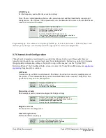
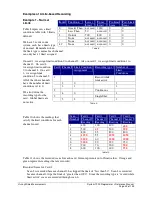
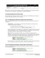
Table 15 represents a limit
conditions table with 1 limit
defined. Range limits only have
the lower limit set.
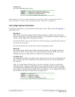
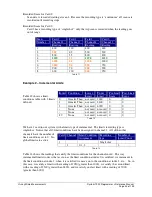
We have 1 card in our system with a limits type of range. The limits recording type is singleshot. All
of the other channels
have the number of limit
conditions set to 0. No
global limits are active.
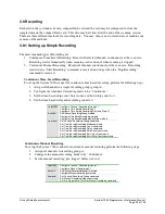
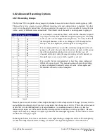
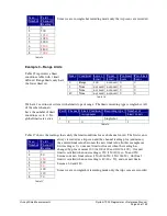
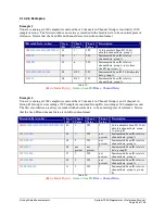
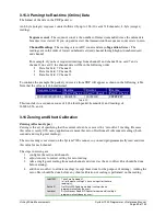
Table 17 shows the readings that satisfy the limit conditions for each channel in red. The first scan is
always recorded as a trip scan and the channel reading plus (and minus)
the entered limit value becomes the new limit value. In this example our
first reading is 0, so our next limit will occur when the reading has
changed by plus or minus 100 (0+100=100 and 0-100=-100). Our next
limit is satisfied when our reading is 150 (150>100), so 50 and 250
become our new limit values (150+100=250, 150-100=50). Our final
limit is satisfied when our reading is 40 (40 < 50), and our new limits
become -60 and 140.
Since we are in singleshot recording mode only the trip scans are recorded
Scan
Number
Card 1
Channel 2
Reading
1
0
2
500
3
1050
4
1090
5
2000
6
2500
7
4800
8
7000
Table 14
Index Condition Lower
Limit
Upper
Limit
Pre-Limit
Scans
Post-Limit
Scans
0
Range
100
not used 0
0
1
None
not used not used 0
0
:
None
not used not used 0
0
49
None
not used not used 0
0
Table 15
Card Channel Limit Condition
Assignment
Recording type
Number of
Limit Conds
1
Singleshot
2
0
1
Table 16
Scan
Number
Card 1
Channel 2
Reading
1
0
2
50
3
150
4
200
5
40
6
100
7
110
8
70
Table 17

