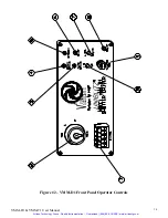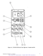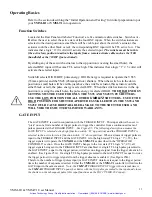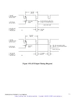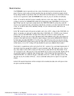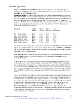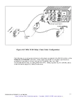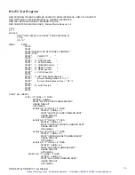
VMM-D1 Front Panel Operator Controls
Description
(Refer to Figure #2)
1.
CONTROL
Terminal block.
The five position terminal block referred to on the driver (and
throughout this manual) as CONTROL provide access to several of the input and output
connections for external operation of your driver. Each terminal is explained below:
a. CONTROL #1 Output.
+10VDC provided for remote switching applications or control
circuits.
b. CONTROL #2 Pulse In. Active high input to control shutter exposure for duration of
positive pulse, or electronic or mechanical switch contact closure. Shutter will follow pulse
and frequency applied to this input. (This will operate the same as the PULSE IN BNC set
to the active high mode.)
c. CONTROL #3 GND. This convenient ground point allows user to connect input or output
signals to ground (common) the
VMM-D1
circuit.
d. CONTROL #4 Input. DC interrupt voltage. With key switch set to mode B, the interrupt
will be activated when input DC voltage (+8VDC min.) is disrupted via a switch, transistor,
or similar method.
This input is for DC voltage only
.
e. CONTROL #5. Output. When interrupt is activated, this normally low output is high until
reset deactivates the interrupt.
2.
MODE Keyswitch.
The position of the key switch sets the mode of interrupt. The interrupt
switch disables the shutter driver when a voltage interrupt is detected, either AC or DC. Upon
reset, the shutter will return to the position set by an external input or the position of the
N.O./N.C toggle switch.
a.
A
(AC interrupt mode). Prevents the driver from re-opening the shutter immediately
upon power-up if the line voltage were to be interrupted. The driver remains disabled until
user supplies reset by specified means.
b.
B
(DC interrupt mode). When the key switch is in Position B the driver will become
disabled when it detects that the DC input voltage at CONTROL #4 has been removed or
disrupted. When the voltage level is re-applied, the driver remains disabled until reset. The
DC input voltage is supplied (from CONTROL #1) or from an external source, determined
by the user.
c.
STD
The STD mode bypasses the driver's interrupt capabilities. CONTROL #4 and
CONTROL #5 become inactive. The
VMM-D1
will not remain disabled after a disruption
in line voltage.
3.
SYNC. ACTIVE
LED indicator. Indicates status of Solid State Sync. output. The green LED
is illuminated when shutter's electronic sync. is activated. (This LED functions only if the
shutter used is equipped with the Solid State Sync. system.)
4.
DRIVER ACTIVE
LED indicator. This LED indicates when the internal shutter driver circuit
input has an active signal present.
5.
DISABLED
Indicator. Indicates that one of the two interrupt modes (mode A or mode B) has
disabled the driver. LED is off after reset, and STD operation.
VMM-D1 & VMM-T1 User Manual
15
Artisan Technology Group - Quality Instrumentation ... Guaranteed | (888) 88-SOURCE | www.artisantg.com

