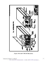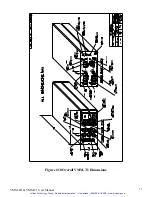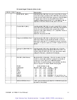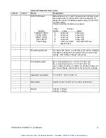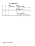
General Characteristics
*
Commands
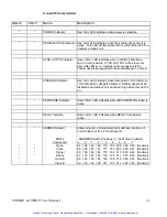
DISABLED Indicator
Red 3mm LED indicates when interruption of AC (Mode A)
or DC (Mode B) voltage is detected. Shutter driver will be
disabled and Interlock Out will be set high when this LED is
on.
x 0 1 2 3 4 5 6 7
*
VMM-D1 VMM-T1
Name Description
*
*
Close
65 129 145 161 177 193 209 225 241 (Decimal)
*
*
*
POWER Indicator
Green 3mm LED indicates when EXPOSURE time base is
active.
*
*
Reset
Red 3mm LED indicates when power is available.
67 131 147 163 179 195 211 227 243 (Decimal)
*
Open B
68 132 148 164 180 196 212 228 244 (Decimal)
*
Close B
*
*
*
DELAY Indicator
Green 3mm LED indicates when DELAY time base is
active.
69 133 149 165 181 197 213 229 245 (Decimal)
DRIVER ACTIVE Indicator Red 3mm LED indicates when the shutter driver circuit is
active. This LED will illuminate with or without the load of a
shutter's actuator coil.
*
Allows selection of individual (local) address locations of
commands sent by a PC's serial port.
*
SYNC. ACTIVE Indicator
Green 3mm LED indicates when a shutter's Electronic
Sync. circuit is active. SYNC. OUTPUT will be low only
when this LED is on. Indicator will only operate if the
shutter used is equipped with the solid-state sync. contact.
RS232
ADDRESS Switch Positions (x = don't care or global)
*
Open
64 128 144 160 176 192 208 224 240 (Decimal)
*
EXPOSURE Indicator
*
Trigger
66 130 146 162 178 194 210 226 242 (Decimal)
*
*
ADDRESS Select
VMM-D1 & VMM-T1 User Manual
40
Artisan Technology Group - Quality Instrumentation ... Guaranteed | (888) 88-SOURCE | www.artisantg.com

