background image

Page 11  


Once the measurement is determined to be Positive or Negative, the shutter will close, the warning LEDs 
will turn off and the result will be displayed and saved.  
 
Typical measurement times in Action Level (PCS) Mode take 1 to 3 nominal seconds; the closer the 
measured value is to the action level, the longer the testing time will be. The maximum measurement time 
in Action Level mode is five nominal seconds without iRTA and ten nominal seconds with iRTA. The 
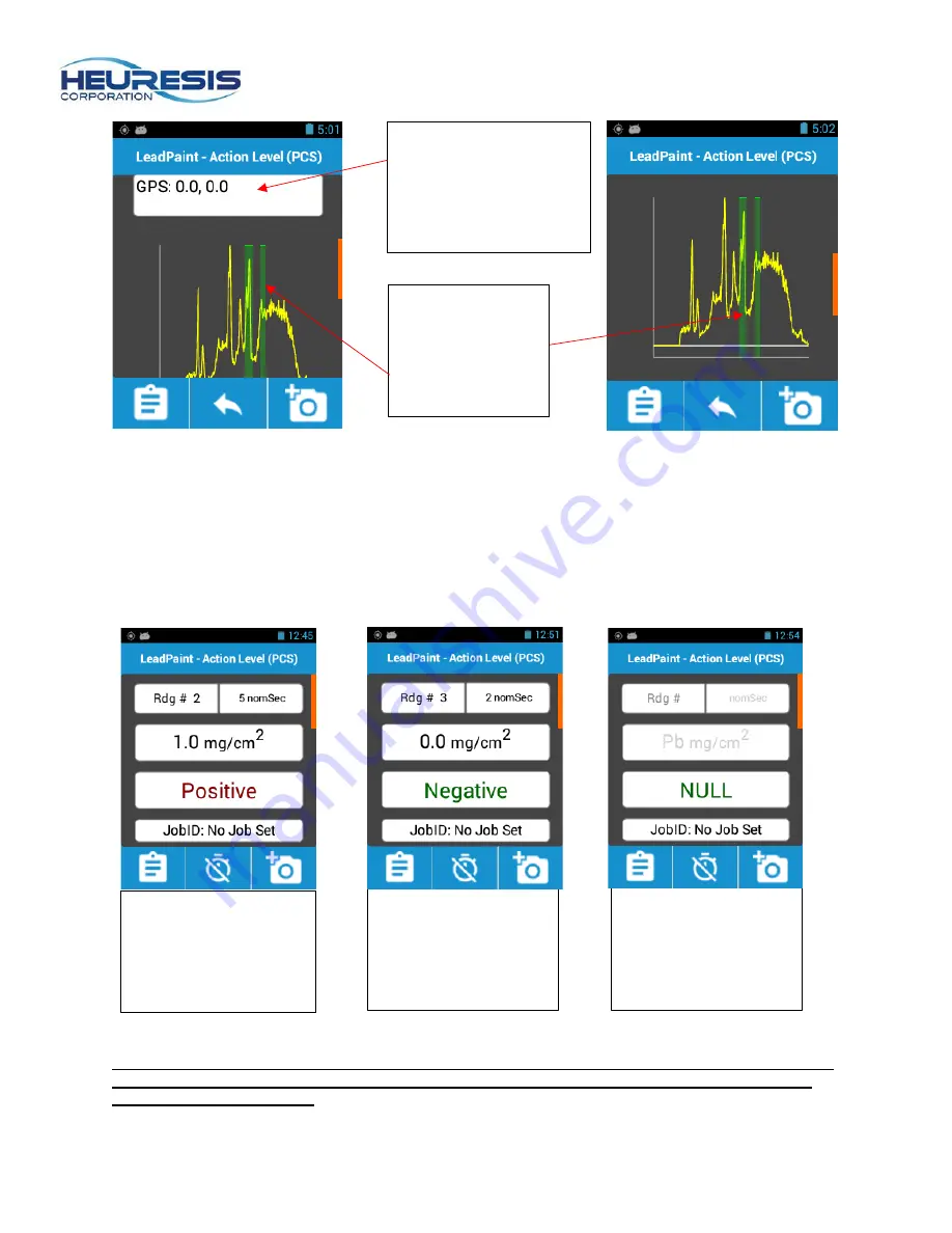
results shown in the examples in Figure 25, 26, and 27 are based on an action level of 1.0 mg/cm

2

.  


Caution:  The Action Level can be changed on the Pb200i by a user with administrative rights, but 
the Pb200i’s Performance Characteristic Sheet (PCS)  only pertains to lead inspections with an 
Action Level of 1.0 mg/cm

2

.

 [This is true for all XRF lead paint analyzers with a PCS.] 

Green vertical 

bars indicate lead 

Kα and Kβ peaks 


Scroll bar 

GPS Coordinates 

(shown as 0.0, 0.0 as 

the Pb200i was not 

connected to satellites 

during the reading) 

Figure 27


“Null” – Reading was  

terminated before the 

instrument had made a 

Positive or Negative 

determination. NULL 

readings are not valid.  

Figure 26


“Negative” – lead 

below selected Action 

Level.  

Figure 25


“Positive” – lead 

present. Result at or 

above the selected 

Action Level.  

Figure 23


Figure 24


Summary of Contents for Pb200i

Page 1: ... the Pb200i be sure to read this entire User s Guide We strongly recommend that you store this User s Guide with the instrument in its carrying case For Sales Service Contact 2650 E 40th Ave Denver CO 80205 Phone 303 320 4764 Fax 303 322 7242 1 800 833 7958 www geotechenv com ...

Page 2: ...Data 21 Using Wi Fi Connectivity 23 Enabling Bluetooth Connectivity 26 Creating an Administrator 29 Changing passwords user name 31 Creating a User Supervisor 32 Changing the Action Level in Action Level Mode 35 Extended Reading Mode 37 Stop at Set Level 37 Fixed Time 38 Stop at Statistics 39 Additional Features 40 Custom Exporting 40 Camera 41 Radiation Safety 43 Operating Conditions Other Safety...

Page 3: ...Figure 1 Trigger LED indicator warning lights Active Measurement Area for sample Proximity button Snout protector label with IRTA markings if applicable Instrument label includes serial numbers Foot stabilizer Camera Lanyard ...

Page 4: ...Proximity button indicator Battery indicator Pb200i App Back Return button Home button Menu button Battery door opening CE mark Battery wedge Caution removing the Battery wedge may cause the battery pack not to fit correctly Mini USB port Battery door ...

Page 5: ... will shorten the useful life of the battery pack 3 Caution We recommend using the Refresh button on the battery charger at least once every two to three months The refresh process typically takes 12 hours There are four green refresh buttons one per each bank of four batteries 4 Once the batteries are fully charged they are ready for use in the Pb200i We recommend leaving the charger plugged in a...

Page 6: ... 9 Apply slight upward force to seat the battery holder properly when fully inserted the battery pack should sit firmly against the battery ledge Fig 10 Secure the battery holder in place with the battery wedge Replace the battery door Fig 11 The latching mechanism will click when the battery pack is seated properly Caution Inserting the battery holder with the incorrect orientation will not damag...

Page 7: ...he keyboard Fig 13 c Review the Warning Screen and confirm that you understand that the instrument produces ionizing radiation when the safety shutter is open and the warning lights are on Fig 14 If you are not familiar with the radiation safety please press I Do Not Understand and read the Radiation Safety section in this User Guide before you return to this screen If and when you do understand t...

Page 8: ...st the sample surface The Power indicator LED Proximity button indicator will turn green when the proximity button is properly depressed Fig 16 2 Pull the trigger Caution the proximity button must be depressed before pulling the trigger When the Pb application is running on the Pb200i and the trigger is pulled with the proximity button depressed the shutter will open The LEDs on the left and right...

Page 9: ...eeping the device s snout in firm contact with the block while continuing to hold the trigger Fig 19 The reading will automatically terminate Fig 20 when the device has determined whether the sample is classified as Positive when Pb 1 0 mg cm2 or Negative when Pb 1 0 mg cm2 2 Compare the result to the value on the reference block and make a note of the reading 3 Complete the test 3 times then aver...

Page 10: ...he bottom up will allow the user to view the GPS coordinates Fig 23 and spectrum of the reading taken Fig 24 Result Action Level indicates Positive or Negative result NULL indicates the reading was terminated before a determination could be made Measurement reading time in nominal seconds Reading sample number If your instrument is equipped with the internal read through adaptor iRTA it will displ...

Page 11: ...on level of 1 0 mg cm2 Caution The Action Level can be changed on the Pb200i by a user with administrative rights but the Pb200i s Performance Characteristic Sheet PCS only pertains to lead inspections with an Action Level of 1 0 mg cm2 This is true for all XRF lead paint analyzers with a PCS Green vertical bars indicate lead Kα and Kβ peaks Scroll bar GPS Coordinates shown as 0 0 0 0 as the Pb200...

Page 12: ... top of either circle in the on or off position to ensure that the iRTA is fully engaged or disengaged Take a measurement in Action Level mode with the iRTA in the off disengaged position as seen in Fig 29 If there is lead in the sample which concentration falls within 20 of the action level the unit will take a 5 second measurement Fig 31 If the reading is outside of 20 of the action level the Pb...

Page 13: ...paint condition and cause if the paint is deteriorated or other parameters The Data Entry function on the Pb200i is a powerful recording tool designed to help the inspector expedite the documentation process such that the inspector can become more efficient recording the details required for their inspection work Data fields can be classified in one of three ways Alphanumeric The inspector can ent...

Page 14: ...HDMS User Guide software version 3 2 or later for additional details To use data entry select Test Fig 37 then tap the clipboard icon Fig 38 Fig 39 shows an alphanumeric data entry field and a SmartField Figure 37 Figure 38 Figure 39 Once you have selected entered the appropriate data entry fields for your next measurement you may initiate the reading from the data entry screen there is no need to...

Page 15: ...top of the black Pelican XRF case as shown in Fig 17 for all calibration check readings Make sure the RTA is OFF disengaged for all calibration check readings Caution Failure to properly position the Pb200i on it s supplied calibration test block and or failure to place the test block on the black Pelican carrying case may cause the instrument to fail the calibration check Perform three measuremen...

Page 16: ...for workflow associated with the JobID functionality Null Readings Null readings where the Pb200i did not complete it s Positive Negative determination must be acknowledged on the display Fig 46 To disable this functionality please see the section on Test Screen Display Figure 43 Figure 44 Figure 45 Figure 46 ...

Page 17: ... reading select the Menu button Fig 47 and Delete Last Fig 48 Stopping a Job Select the Job icon to stop the current job Fig 49 Follow the Calibration Check prompts on the display after stopping the job Fig 50 Figure 47 Figure 48 Figure 49 Figure 50 ...

Page 18: ...00i by pressing the Back Return button until you get to the Main Screen Caution Always export data before connecting the Pb200i to your PC If you connect your PC prior to exporting readings you may not retrieve the entire data set On the main menu select Readings Fig 51 then Export Readings Fig 52 Select the range of readings you wish to include in the export Fig 53 and whether or not you wish to ...

Page 19: ...king the Export Spectrum box will include two additional lines of data associated with each reading The Export Spectrum feature is turned off by default The data is exported to a Readings directory folder Fig 55 Figure 55 ...

Page 20: ...pplied with your Pb200i Connect the USB cable to the PC The driver will install automatically You may also get a message on your Pb200i that reads Allow USB debugging the first time you connect to your PC Fig 57 Select Always allow from this computer and then select OK When connecting the Pb200i to a PC it will appear as though you ve plugged in an external drive Fig 58 Select internal storage the...

Page 21: ...ore attempting to open these files Caution Check to make sure that all of the data intended for export is included in the download If it is not unplug the analyzer from the USB cable and repeat the steps above You may also use Heuresis HDMS software to retrieve the readings from your Pb200i in a tamperproof format retrieve your previously exported csv file customize the order and content of export...

Page 22: ...trum checked select Export Fig 64 Your Pb200i will tell you if it has successfully exported the readings Fig 65 Select OK To retrive the debug readings repeat the process described in Transferring the Data to retrieve the extendRdg csv The readings will be in the same Readings file location Fig 66 Figure 65 Figure 64 Figure 66 ...

Page 23: ...d in Fig 68 Find the desired network select and connect Fig 69 Enter any required Wi Fi password to proceed Exit from Wi Fi using the left arrow then close the settings app by holding the center Home button down until a list of open apps appears Figure 70 Swipe left to close the Settings app Caution Turning on Wi Fi will decrease the battery life of the Pb200i We recommend leaving the Wi Fi featur...

Page 24: ...from off to on Fig 72 Caution The FTP server feature will default to the off position for security reasons every time the instrument is turned on Place the number which appears in the area circled in Fig 73 in your web browser The example shown here is ftp 10 1 10 13 2121 Figure 71 Figure 72 Figure 73 ...

Page 25: ...nd password Fig 74 Enter ftp as the User name and ftp as the Password Select Log on Your screen should display the file tree located on your Pb200i as shown in Fig 75 Be sure to bookmark this page in your browser Select the readings folder Figure 74 Figure 75 ...

Page 26: ...ciated with the exported readings Enabling Bluetooth Connectivity The Pb200i is equipped with a Bluetooth radio You can use this feature to pair the instrument to an external keyboard or other Bluetooth device Caution There are multiple Bluetooth equipped devices on the market but they are not all compatible with the Pb200i To enable Bluetooth select the Settings icon Fig 77 Figure 76 Figure 77 ...

Page 27: ...k on Bluetooth Fig 78 A list of available devices will populate on the screen click on the Pb200i Fig 79 This makes the instrument visible to other devices Click on the desired device to pair it with your Pb200i Fig 80 Figure 78 Figure 79 Figure 80 ...

Page 28: ... On by default at the factory Follow these steps to turn on off the GPS receiver Select the Settings icon Fig 81 Scroll down to Location Access Fig 82 and select Slide Access to my location to ON Fig 83 The icon in shown in Figure 84 will appear when GPS is enabled Figure 81 Figure 82 Figure 83 Figure 84 ...

Page 29: ...strator and can administer rights to other users as needed This person should be a high level employee responsible for the instrument such as the radiation safety officer RSO Login using the default password When prompted to create user select yes Enter the text for your new password Contnue by loging in using the new password Fig 89 to 91 Caution User names must be a minimum of four characters Pa...

Page 30: ...nally settings Figures 92 to 95 As an administrator or Supervisor you can turn ON OFF any of the available options To save select the back arrow on the analyzer and exit the menu Fig 96 and 97 For more information on Permissions and Settings please see Appendix A Figure 92 Figure 93 Figure 94 Figure 95 Figure 96 Figure 97 ...

Page 31: ...word or user name From the main menu select Setup Users Change Password or Change Username Fig 98 to 100 Select Update Caution User names must be at least four characters long and passwords must be at least six numbers long Figure 98 Figure 99 Figure 100 Figure 101 Figure 102 ...

Page 32: ...he instrument on a user by user basis to reduce potential for error such as a User accidentally deleting stored readings To create a Supervisor ID on the Pb200i start at the Main Menu Select Setup Users Create User Select Supervisor and create a new password Fig 103 to 107 Caution Only an administrator can set up these rights Figures 64 to 68 Figure 103 Figure 104 Figure 105 Figure 106 Figure 107 ...

Page 33: ...ermissions for themselves a Supervisor or a User A Supervisor can only modify the permissions for a User The example shown here illustrates the administrator revoking the default permission to delete data for a user s ID Start at the main menu Select Setup Users Modify Permissions Fig 113 to 116 Select the user and change Allow to Disallow Fig 117 to 119 The factory default settings are shown in F...

Page 34: ... Back out using the Back button Fig 120 to save then go to Settings and select User Fig 120 to 121 Figure 113 Figure 114 Figure 115 Figure 116 Figure 117 Figure 118 Figure 119 Figure 120 Figure 121 Figure 122 ...

Page 35: ...s no longer available Fig 127 Changing the Action Level in Action Level Mode In some instances the user will want to change the action level to accommodate a Pb threshold other than the default of 1 0 mg cm2 In order to change the action level start at the main menu select Setup Mode Action Level Mode tap the gear icon and input the number Fig 128 to 133 Press the Back button Fig 134 Figure 123 Fi...

Page 36: ... action level is set to anything other than 1 0 mg cm2 the instrument will display NEG for negative and POS for positive In this example the action level has been set to 7 mg cm2 Fig 99 to 101 Figure 99 Figure 100 Figure 101 Figure 132 Figure 133 Figure 134 Figure 135 Figure 136 Figure 137 Figure 138 Figure 139 Figure 110 ...

Page 37: ...rd deviations above the action level and number of standard deviations below the action level Once these user determined thresholds have been reached the instrument will stop acquiring data close the safety shutter and display a result This mode may be useful for customers performing commercial industrial and or institutional Pb inspection work where they are looking for the Pb200i to terminate th...

Page 38: ...e that can be entered is in real time seconds up to a maximum of 300 seconds 5 minutes This mode is often employed when users are following a strict standard operating procedure SOP that prescribes the length of each reading that must be taken on a given project To setup this mode start at the main menu Select Setup Mode Fixed Time Enter the desired time limit in seconds Fig 144 to 146 then select...

Page 39: ...the Unlimited Time mode start at the main menu Select Setup Mode Unlimited Time Fig 148 Select the Back button Stop at Statistics Stop at Statistics mode automatically terminates the measurement when there is no statistical advantage to sampling for additional time This may be beneficial to customers looking for low levels of Pb in commercial industrial and or institutional inspection work To setu...

Page 40: ...iles You may select any of the options shown in Fig 152 by following the prompts Use of the JobID field permits you to export readings on a job by job basis see Creating a Job and Performing a Calibration Check for more information on using the JobID field Figure 130 Figure 151 Figure 152 Figure 153 Figure 154 ...

Page 41: ...oto or the X to exit the camera Once you have stored the photo select whether you want it associated with the next or the last XRF reading Fig 158 Note Please refer to the section on Exporting Readings and the HDMS User Guide for more information on retrieving photos captured during your inspections Swipe to View Readings from Test Screen You may swipe left or right from the Ready to Test screen t...

Page 42: ...asurements for a lower level of lead The factory default for this setting is ON Precision displays hides the two sigma 95 confidence It is often turned ON in combination with Positive Negative OFF The factory default for this setting is OFF We don t recommend turning it ON in conjunction with Positive Negative set to ON as Action Level mode already takes into account the Pb200i s two sigma confide...

Page 43: ...tch must be pressed before the trigger is pressed or the shutter will not open The shutter of the device will automatically close when a reading is complete even if you continue to hold the instrument against the sample The large majority of the instrument readings will take less than two seconds The Pb200i is designed so you cannot accidently open the shutter The instrument requires a password to...

Page 44: ...ght 0 48 0 025 0 01 Top 0 25 0 025 0 01 Bottom 0 55 0 025 0 01 Front 1 0 0 035 0 01 Rear 0 05 0 015 0 01 Typical dose rates 5 milliCuries 185 MBq source with the shutter open taking a reading on wood in milliREM hr are as follows 5 cm 30 cm 100 cm Left 1 3 0 045 0 01 Right 1 7 0 06 0 01 Top 1 9 0 055 0 015 Bottom 0 70 0 04 0 01 Rear 0 20 0 025 0 01 ...

Page 45: ...ent Always observe the status of the warning lights Always transport the device in accordance with the regulations of the jurisdiction in which you are located Always transport the device in the hard plastic case supplied with the instrument This case can be transported in a cardboard and foam over pack for additional protection Be sure to use all transportation labels required by the regulatory j...

Page 46: ...o determine the required use and type of dosimeters Always follow the instructions provided by the vendor when using dosimetry badges Dosimeters should be returned to the vendor for analysis Dosimetry badges are changed on either a monthly or quarterly basis The correct option depends on the dose received If dosimetry is used most users require a quarterly change but this also depends on whether t...

Page 47: ...c 3008 Cornwallis Road P O Box 12057 Research Triangle Park NC 27709 A copy of the leak test results must be kept on file at your primary location of storage It is also useful to keep a copy of the leak test results with the instrument as this may be required or desired in certain transport situations Heuresis recommends keeping a copy of the leak test results inside the instrument transport case ...

Page 48: ...Page 48 Figure 167 ...

Page 49: ...ons Major damage If the instrument is not intact i e the snout of the instrument is broken open crushed melted etc do the following 1 Do not touch or move the instrument 2 Establish a 10 2m control area around the damaged instrument 3 Do not leave the area unattended 4 Approach the instrument only with a radiation survey meter capable of measuring in the millirem range Make sure you have proper tr...

Page 50: ...artin 1 617 751 8286 call or message any time You should also know the contact information for the police and fire departments where you are using the instrument Police____________________________ Fire____________________________ Other contacts _____________________________________ __________________________ _____________________________________ __________________________ Your organization contact...

Page 51: ...l Seller have any obligation to make repairs replacements or corrections required in whole or in part as the result of i normal wear and tear ii accident disaster or event of force majeure iii misuse fault or negligence of or by Buyer iv use of the Products in a manner for which they were not designed v causes external to the Products such as but not limited to power failure or electrical power su...

Page 52: ...Permissions for that User The Administrator can also set up the initial settings on the instrument This allows each user to have the initial settings be consistent with all users Unless restricted by permissions set by the Administrator the User can change the settings A less basic configuration allows the Administrator to add a Supervisor level above the User The Supervisor can set permissions fo...

Reviews: