58 | 140285
EN
User manual
1
Symbol clarification
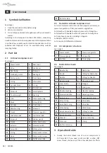
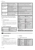
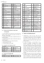
See image 1
1. Read the manual carefully before using.
2. Wear ear protectors.
3. Do not dispose of electrical appliances with your domestic
waste!
According to the European Directive 2012/19/EU, concerning
used electrical and electronic appliances and its implementation
in national law, superannuated electrical appliances must be
collected and disposed of via an environmentally suitable
recycling facility.
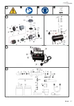
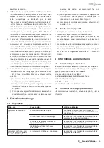
2 Part List
2.1
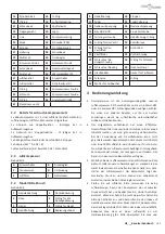
Airbrush compressor set
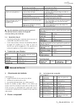
See image 2
1
Power switch
2
Rear cover
3
Wire
4
Condenser
5
Rear body
6
Screw x4
7
Stationary motor
8
Bearing x2
9
Rotary motor
10
Front body
11
O-ring
12
Valve plate
13
Cylinder block
14
O-ring
15
O-ring
16
Air-inlet cap
17
Screw x4
18
Head cylinder
19
Counterweight
20
Bearling
21
Link
22
Compression ring
23
Block
24
Screw (#58)
25
Cylinder
26
Front cover
27
Retainer ring
28
Screw x4
29
Nut x4
30
Pressure regulator
31
Inlet valve rob1
32
Inlet valve rob2
33
Screw x4
34
Rubber pad x4
35
Nut x4
36
Water-drain valve
37
Air tank
38
Pressure switch
39
Air splitter
40
Safety valve
41
O-ring
42
Compression screw
43
Hose
44
Compression screw
45
O-ring
46
Outlet valve rob2
47
Out-lets valve
2.2 Details for airbrush compressor set
1x mini compressor with 3 liter air tank (copper coil motor), air
pressure regulator, air filter, manometer, original box.
1x Airbrush with double-function-8 piece set in storage box.
1x Airbrush with double-function-11 piece set in storage box.
1x 3-way hose connector including 2 stoppers.
1x Adaptor (M5*0.5-G1/8)
1x Connector (G1/8female-G1/4male)
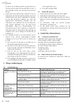
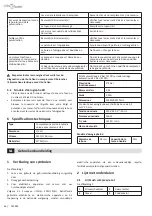
2.3 Air compressor structure
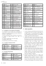
See image 3
A
Power switch
B
Pressure regulator
C
Pressure gauge
D
Connection
E
Air filter
F
Power plug
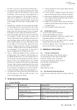
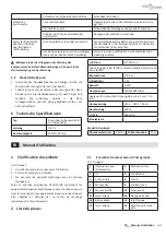
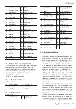
2.4 Model BD air bursh
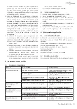
See image 4
1
Needle Cap
2
Nozzle Cap
3
Nozzle
4
O-Ring for Nozzle Cap
5
Needle
6
O-Ring for Needle
7
Needle Guide
8
Operation Lever
9
Lever Guide
10
Stopper
11
Spring
12
Spring case
13
Needle chucking
14
Needle chucking
15
Standard-Handle
16
Adjusting screw
17
Guide Screw
18
Lever Guide O-ring
19
Valve O-ring
20
Valve Body
21
Valve Rod O-ring
22
Valve Rad
23
Valve Spring
24
Valve Screw
25
Hose Connector Nut
26
O-Ring for Hose
27
Hose connector
28
Nozzle Spanner
29
Glass Jar
30
Lid for Color Cup
31
Color cup
32
O-ring
33
Nut for color cup
3
Operation Guide
1. Usually the outlet thread size of our air compressor is
3.175mm BSP. If you need a 6.35mm BSP or other NPT
screw thread, choose any of the other adapters to affix to
Summary of Contents for 140285
Page 47: ...47 140285 1 vidaXL vidaXL 2...
Page 48: ...48 140285 5 40...
Page 49: ...49 140285 8 1...
Page 50: ...50 140285 vidaXL vidaXL 2...
Page 51: ...51 140285 5 C 40 C 8...
Page 114: ...114 140285 4 4 1 47 dB 4 2 bd 5 5 1 220 240V 6 6 5 2 BD 6 1 6 HP 1450 1700 rpm 20 23...
Page 117: ...117 BG___ e 3 1 BD 1 2 3 4 5 4 4 1 47 dB 4 2 Bd 5 5 1 220 240V 6 6...
Page 126: ...126 140285...
Page 127: ...127 140285...

