Andex 774
Assembly instructions
Original assembly instructions
Edition
01.2012
Date of print
01.2013
Language
EN
Machine number
VF65852501 –
Model
VF6585
Document number
VF16648059.EN
Page 1: ...Andex 774 Assembly instructions Original assembly instructions Edition 01 2012 Date of print 01 2013 Language EN Machine number VF65852501 Model VF6585 Document number VF16648059 EN ...
Page 2: ...up Gottmadingen N V Germany Reproduction transfer to other media translation or the use of extracts or parts of this manual without the explicit permission of Kverneland is not permitted All rights reserved The contents of this operating manual are subject to change without notice The right to technical revision is reserved ...
Page 3: ...ransport chassis 11 Steering 16 Gear box 22 Lighting equipment and electrics 24 Lift arms and hydraulic cylinders 26 Hydraulics 29 Rotor 32 Drive 40 Attachment parts 41 Quick Set 46 Overview 46 Setting up work 47 Length of the PTO shaft 47 Checking the track 49 Swath formers 50 Fitting the tine supports 52 Additional equipment 54 Fitting additional equipment 54 Circuit diagrams 67 Hydraulic circui...
Page 4: ...ne Meaning of the symbols In these assembly instructions the following symbols and terms have been used A bullet point accompanies each item in a list A triangle indicates operating functions which must be performed A plus sign indicates additional equipment which is not included in the standard version We have also used pictograms to help you find instructions more quickly The Information pictogr...
Page 5: ...ations as well as generally applicable health and safety and road safety regulations All personnel involved in the assembly must be aware of these rules and regulations and adhere to them they must also be instructed on the potential risks and dangers Unauthorised alterations to the machine invalidate any liability of the manufacturer for resultant damage Danger indicators signify the risk of seri...
Page 6: ... operating the machine Wear sturdy footwear and prescribed protective equipment Support and secure the machine carefully during assembly Particular care must be taken in dealing with energy accumulators such as springs and hydraulic or compressed air assemblies Dispose of oils grease and filters in accordance with regulations Protective equipment must be properly attached and swung into its protec...
Page 7: ... bottom Rotation about a horizontal axis viewed at right angles to the direction of travel from left to right The rotation of screws and nuts etc is always viewed from the operating side 8 8 10 9 12 9 M 6 9 9 Nm 7 3 ft lbs 14 Nm 10 3 ft lbs 17 Nm 12 5 ft lbs M 8 24 Nm 17 7 ft lbs 34 Nm 25 ft lbs 41 Nm 30 3 ft lbs M 10 48 Nm 35 4 ft lbs 68 Nm 50 2 ft lbs 81 Nm 59 8 ft lbs M 12 85 Nm 62 7 ft lbs 120...
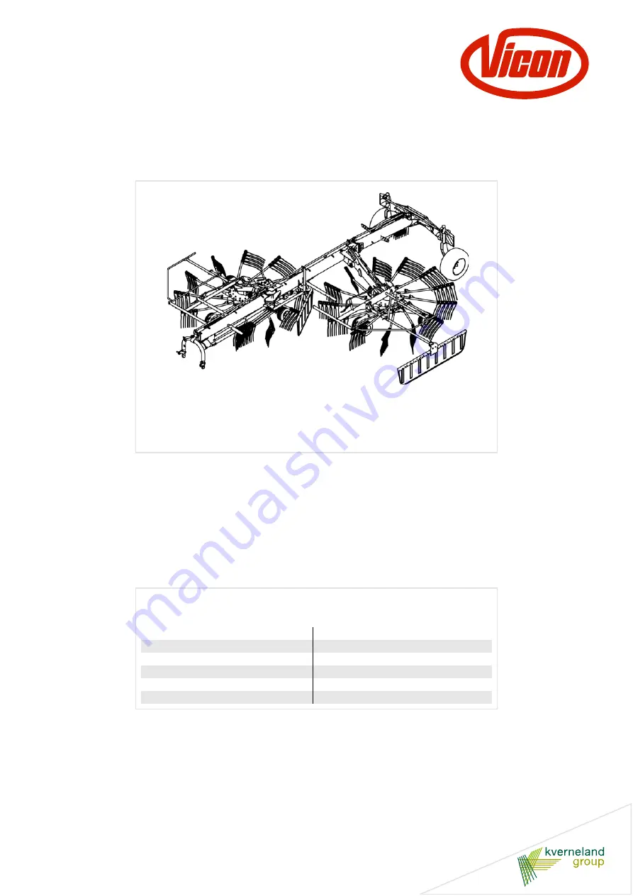
Page 8: ...tor Attachment carrier Folding parking stand Transport holder for tine supports Main frame Rear swath former Deflector bar Transport chassis Rotor chassis Lift limiter T gear box Steering arm Lift arm console Steering Front swath former Tine support ...
Page 9: ...e REPORT MISSING PARTS form and send it to the ORDER DESK in Kerteminde straight away Removing the surface protection Remove the surface protection e g Tectyl with which the bare surfaces such as tine arms tine supports and bearing shafts have been coated Grease the bare surfaces using a brush Observe the safety information Observe the safety information when carrying out all work Disregard for sa...
Page 10: ...ort chassis Rotor gear T gear box Centre PTO shaft Left hand PTO shaft Centre main frame Rear main frame Front main frame Left hand lift arm T gear box Left hand rotor chassis No Assembly group Page 1 Main frame and transport chassis 11 2 Steering 16 3 Gear box 22 4 Lighting equipment and electrics 24 5 Lift arms and hydraulic cylinders 26 6 Hydraulics 29 7 Rotor 32 8 Drive 40 ...
Page 11: ...n frame with lifting accessories and secure it with two stands Raise the front main frame with lifting accessories and bolt it to the centre main frame torsion free Fit the bracket for the tine covers on the left in relation to the direction of travel Transport chassis Centre main frame Stand Rear main frame Front main frame Centre main frame Front main frame Bracket No Quantity Part 1 1 Centre ma...
Page 12: ...chment carrier Fit the attachment carrier to the main frame Fit the hose guide onto the attachment carrier Front main frame Split pins Washer Washers Parking stand No Quantity Part 1 1 Parking stand 2 2 40 x 58 1 6 washers 3 1 40 x 58 4 washers 4 1 Split pins Attachment carrier Hose guide No Quantity Part 1 1 Hose guide 2 1 Perforated plate 3 2 M 10 x 30 rounded head bolts 4 2 11 x 20 x 2 washers ...
Page 13: ... the flange piece torsion free Fit the bracket for the tine covers on the right in relation to the direction of travel Secure the rear main frame with a stand Rear main frame Centre main frame Bracket No Quantity Part 1 1 Rear main frame 2 1 Centre main frame 3 12 M 16 x 60 bolts 4 12 M 16 nuts 5 20 M 16 washers 6 1 Bracket for tine covers ...
Page 14: ...ransport chassis onto the axles Fit the brackets for the wheel chocks Fit the top cover plate Spacer sleeve Stowage holder Top cover plate Bottom cover plate No Quantity Part 1 1 Transport chassis preassembled 2 1 Main frame preassembled 3 2 Stowage holders 1 x left hand side 1 x right hand side 4 6 M16 x 140 bolts 8 1 Bottom cover plate 9 2 M16 x 80 bolts 10 2 Spacer sleeves 11 14 M 16 washers 12...
Page 15: ...ckaging 15 Overview of transport chassis Drive in the dowel pins at 90 to each other Spacer sleeve M 16 290 Nm M 16 210 Nm M16 x 120 Dowel pins Wheel chock M18 300 Nm wheel nuts Spacer sleeve M16 x 140 M16 x 80 ...
Page 16: ...s page 17 Fit the steering rod See Fitting the steering rod page 19 Connect the steering rod See Connecting the steering rods page 20 Fit the steering rod to the attachment carrier See Fitting the steering rod to the attachment carrier page 21 Front steering rod Rear steering rod Steering arm Right hand track rod Left hand track rod Bearing shell Middle steering rod Please note left hand thread ...
Page 17: ...locking nuts The track rods and steering rod must be fitted in such a way that the rods are free to move without play after being secured Otherwise the machine may be damaged No Quantity Part 1 1 Steering rod 2 2 Track rods 3 2 Spacer sleeves 4 1 Threaded pin with lubricating nipple for steering rod 5 2 Threaded pins with lubricating nipple for track rods 6 3 M 12 washers 7 3 M 12 self locking nut...
Page 18: ... arm Fit the clevis to the outside of the right and left hand track rods Insert the pin into the track arm and secure with self locking nut Attach the protective cap Check the tracking and adjust if necessary See Checking the track page 49 Locking plates Bolts and washers No Quantity Part 1 2 Locking plates 2 2 M8 x 20 bolts 3 2 Washers 1 x lubricating nipple 3 x lubricating nipple Pin Self lockin...
Page 19: ...s not used Place the steering rod into the bearing shells Fit the upper part of the bearing shells Guide the middle steering rod through the bearing shells Insert the front and rear steering rods Connect the steering rods with pins Connecting the steering rods page 20 No Quantity Part 1 1 Middle steering rod 2 1 Clevis 3 2 16 x 45 x 38 pins 4 2 Split pins 5 3 Bearing shells Middle steering rod 1 2...
Page 20: ...o the pin Secure the threaded pin with a self locking nut On machines which are fitted with the optional night swath equipment a hydraulic steering rod is used in place of the front steering rod See chapter Night swath equipment Installing the hydraulic steering rod on page 58 Do not overtighten the self locking nuts The steering rods must be fitted in such a way that the clevises are free to move...
Page 21: ...ering rod to the 2 point attachment carrier Guide the steering rod into the bracket Insert the pin through the bushed bearing tube and steering rod Secure the pin with dowel pins Steering rod Bracket Pin No Quantity Part 1 1 Steering rod 2 1 Pin 3 1 5 x 28 dowel pin 4 1 8 x 30 dowel pin ...
Page 22: ...of rotation must be observed when fitting the T gear box Use a brush to grease all the PTO stub shafts Fit the T gear box to the transmission console as illustrated Spacer sleeves Bolts T gear box No Quantity Part 1 1 Front T gear box 2 4 M 12 x 40 bolts coated 3 4 Spacer sleeves ...
Page 23: ...o the transmission console as illustrated The rear transmission console is located on the right hand side in relation to the direction of travel Cover the rear gear box stub with the cap T gear box Bolts Spacer sleeves M12 x 40 bolts Cap M8 x 16 bolts T gear box Gear box console No Quantity Part 1 1 Rear T gear box 2 4 M 12 x 40 bolts coated 3 4 Spacer sleeves 4 1 Cover cap 5 2 M8 x 16 bolts ...
Page 24: ...plate to the warning sign Do not fully tighten the nuts Thread the bolts into the elongated holes Fully tighten the nuts Elongated holes Plate No Quantity Part 1 1 Warning sign and lighting equipment set for left and right hand sides 2 4 Bolts 3 4 Washers 4 4 Nuts 5 2 Plates 6 2 Bottom self adhesive reflectors Right hand warning sign Left hand warning sign ...
Page 25: ...rear light cables as illustrated Then plug in the long cable and route it in the cable duct underneath the main frame Secure the cable to the transport chassis with cable ties No Quantity Part 1 1 Cable set 2 Cable tie Cable set Connector Cable duct Ensure the correct position of the plug and bush during connection yellow left hand side green right hand side Cable tie Rear light Rear light ...
Page 26: ...e as illustrated and secure with M8 x 50 bolts Screw the flange pieces in place with M12 x 50 bolts Spacer sleeve Flange piece Lift arm console Right hand lift arm Left hand lift arm Flange piece Bearing shaft M8 x 50 bolts M12 x 50 bolts M8 x 50 bolts Dowel pin Nuts 8 9 No Quantity Part 1 1 Lift arm 2 2 Spacer sleeves 3 2 M60 x 62 x 3 washers 5 2 M60 x 62 x 1 washers 6 2 Flange pieces 7 4 Dowel p...
Page 27: ... bolts 5 Adjusting the control segment Slightly loosen the bolts 5 and move the position of the control segment 1 in the elongated hole in order to change the interval between the times at which the front and rear rotors will be raised Tighten the bolts 5 in the desired position Moving the control segment clockwise shortens the time between the points when the front and rear rotors are raised No Q...
Page 28: ...ashers The lift arm hydraulic cylinders need a cushion of air to enable them to function properly such as folding out on a slope The hydraulic cylinders are ventilated via a valve once the machine has been fully assembled See Introducing air to the hydraulic cylinder page 69 No Quantity Part 1 2 Hydraulic cylinder preassembled 2 2 Lift limiter 3 2 Pin 4 4 31 x 45 x 2 washers 5 2 30 x 50 x 6 washer...
Page 29: ...raulics Most of the hydraulic components are already preassembled Lay the hydraulic hoses and screw them firmly in place Hydraulic circuit diagram page 67 Left hydraulic cylinder Right hydraulic cylinder Single swath option ...
Page 30: ...the front cable duct Fit the front cable duct with hydraulic hoses and electrical cables under the main frame Fit the PTO shaft holder to the front and centre cable duct with coach bolts No Quantity Part 1 1 Front cable duct 2 4 M8 x 16 thread rolling bolts 3 2 PTO shaft holder 4 4 Bolts 5 4 Washers 6 4 Nuts Front cable duct Hydraulic hoses and electrical cables PTO shaft holder ...
Page 31: ...hrough the ceramic eyelet on the attachment carrier Push the cable stopper onto the control cable and secure with knots Secure the traction cables with the cable stopper so that they are slightly tensioned when the lift arm is lowered Ceramic eyelet Transport locking bar No Quantity Part 1 1 Control cable 9 m left hand lift arm 2 1 Control cable 6 m right hand lift arm Cable guide Cable stopper Ce...
Page 32: ... the optional night swath equipment different rotors are used See chapter Night swath equipment Fitting the chassis on machines with night swath equipment on page 61 No Quantity Part 1 2 Preassembled rotor chassis with rotor gear 2 8 16 x 6 5 wheels 3 8 Cover caps Wheel 20 Nm wheel nut Rotor gear Rotor chassis ...
Page 33: ...the running wheels as illustrated to the right hand front rotor chassis Fit the running wheels to the rotor chassis freewheel axles Fit the running wheels to the twin axle Fit the twin axle to the rotor chassis Adjust the rotor pitch See Overview of rotor adjustment page 53 Tighten the wheel nuts on the wheels to 20 Nm Fit cover caps to wheels Rotors with freewheel axles Twin axle 4 x M12 bolts ti...
Page 34: ...otor chassis 20 Nm wheel nut Cover cap Wheel Twin axle Freewheel axle No Quantity Part 1 1 Preassembled right hand rotor chassis with rotor gear 2 2 16 x 6 5 running wheels for freewheel axles 3 2 16 x 6 5 running wheels for twin axle 4 8 Cover caps ...
Page 35: ...the running wheels to the rotor chassis rigid axles Fit the running wheels to the twin axle Fit the twin axle to the rotor chassis Adjust the rotor pitch See Overview of rotor adjustment page 53 Tighten the wheel nuts on the wheels to 20 Nm Fit cover caps to wheels Twin axle 4 x M12 bolts tightened to 85 Nm Rear running wheel ...
Page 36: ...nd rotor chassis 20 Nm wheel nut Cover cap Wheel Twin axle Rigid axle No Quantity Part 1 1 Preassembled left hand rotor chassis with rotor gear 2 2 16 x 6 5 running wheels for rigid axle 3 2 16 x 6 5 running wheels for twin axle 4 8 Cover caps ...
Page 37: ...e rotor Use a brush to grease the PTO stub shaft Fit the bearing housing to the rotor gear on each of the rotors No Quantity Part 1 1 Right hand bearing housing 2 4 M16 x 55 bolts 3 4 Spacer sleeves Bearing housing Rotor gear Spacer sleeve PTO stub shaft M16 x 55 bolts ...
Page 38: ...nto the bearing housing Guide the pin through the pendulum support and elongated hole Place the washers onto the pin and secure the pin using spring cotter pins The illustration refers to the left hand chassis The parts for the right hand chassis are fitted the other way round Drive in the dowel pins at 90 to each other Bearing housing Washer Spacer sleeve Ring Spring cotter pin Washer Pendulum su...
Page 39: ...ing screw The maximum length is 900 mm Raise the machine to the headland position Turn the rotor by hand to check that it is rotating correctly Distance from possible collision points min 150 mm Using the pendulum support adjust the position of the rotor m ax 900 m m Adjusting screw 1 2 3 4 No Quantity Part 1 1 Pendulum support 2 1 Pin 3 2 26 x 38 x 2 washers 4 2 Spring cotter pins Checking the cl...
Page 40: ...gth of the PTO shaft page 47 Fit PTO shaft Fit the PTO shafts for the machine Secure the PTO shaft guards with chains Greasing schedule for PTO shafts Main drive shaft Gear box Gear box Main drive shaft Auxiliary drive shaft No Quantity Part Greasing interval 1 1 Main drive shaft 100 Wide angle joint daily 2 1 Auxiliary drive shaft 100 3 2 Auxiliary drive shaft 100 1 2 3 3 ...
Page 41: ...ame Fit the tine support stowage holders to the front main frame Fit the cover caps Fitting the deflector bar Fitting the stowage holder No Quantity Part 1 2 Deflector bar 2 4 M12 bolts 3 4 M12 washers 4 4 M12 nuts 5 1 Front part of stowage holder 6 2 M10 bolts 7 2 M10 washers 8 2 M10 nuts 9 1 Rear part of stowage holder 10 2 M10 bolts 11 2 M10 washers 12 2 M10 nuts Right hand deflector bar Left h...
Page 42: ...flector carrier from the inside to the outside and connect with washers and self locking nuts Fitting the deflector bar page 44 4 x M12 x 35 bolts No Quantity Part 1 1 Deflector carrier 2 4 M12 x 35 bolts 3 8 Washers 4 4 M 12 self locking nuts 5 1 Deflector bar assembly Deflector carrier Bearing housing Crank locking device Deflector bar ...
Page 43: ...he outside and connect with washers and self locking nuts Fitting the deflector bar page 44 4 x M12 x 110 bolts 2 x M12 x 110 bolts 2 x M12 x 120 bolts No Quantity Part 1 1 Deflector carrier 2 1 Swath former carrier 3 2 M12 x 120 bolts 4 6 M12 x 110 bolts 5 16 Washers 6 8 M 12 self locking nuts 7 1 Deflector bar assembly Deflector carrier Swath former carrier Bearing housing Crank locking device ...
Page 44: ...n the deflector carrier Push the deflector bar into the rear opening Slide on washer at the front and secure with split pin On the rear part of the deflector bar first push on the spring and then the washer Secure the washer with the split pin Spring Split pins Washer No Quantity Part 1 2 Deflector bar 2 2 Springs 3 4 Split pins 4 4 31 x 45 washers Deflector bar Deflector carrier Spring Washer Spl...
Page 45: ...rank On both rotors Fit the crank onto the rubber joint and secure with a dowel pin Secure the crank with the crank locking device No Quantity Part 1 2 Cranks 2 2 Crank locking device 3 2 Dowel pin Crank locking device Crank Dowel pin ...
Page 46: ...them in the correct position See Overview of transport chassis page 15 Final assembly of the rotor chassis The rotor chassis wheels are partially preassembled Fit the wheels to the rotor chassis See Fitting the wheels page 33 Fitting the warning signs When the machine is delivered the warning signs will have been only provisionally fitted Fit the warning signs and lighting equipment in the correct...
Page 47: ...O shaft Lower the tractor s lower link Set the combination tractor and machine to the smallest steering angle Switch off the tractor and secure it against rolling away Switch off the tractor and secure it Before you dismount Switch off the tractor Remove the ignition key Secure the tractor against rolling away An unsecured tractor can run you over or trap you Serious or fatal injury would be cause...
Page 48: ... 20 mm Shorten the slide tube and guard tube by the same dimension Deburr the ends of the tube Remove the swarf Grease the sliding surfaces well Fitting the PTO shaft Make sure that you fit the PTO shaft in the correct installation position The wide angle joint must be fitted on the machine side There is a marking on the guard tube of the PTO shaft Check the length of the PTO shaft and shorten it ...
Page 49: ...ck at the front sides of the tyres Deviating dimensions for machines with serial numbers 2501 2550 L2 3602 mm and L3 1849 mm Track arm Track rod Steering rod Steering arm A A S S Only middle steering rod is adjustable Rear steering rod not adjustable Front steering rod not adjustable L1 2344 mm L2 3610 mm L3 1841 mm welded Track rod S 1 015 mm Front steering rod Middle steering rod Rear steering r...
Page 50: ...ube can be slid into the carrier tube without jamming Slide in the telescopic tube to the desired length and fix it in place with the T bolt For information on adjusting the swath former see chapter Adjusting the swath former in the operating instructions Clamping lever Angle bracket Swath former M12 x 75 bolts T bolt Adjusting screw M10 x 30 bolts No Quantity Part 1 1 Rear swath former 2 1 Telesc...
Page 51: ...in place with the T bolt Check that there is sufficient clearance between the swath former and tine supports The swath former must not touch the tines For information on adjusting the swath former see chapter Adjusting the swath former in the operating instructions T bolt M12 x 35 bolts M12 x 35 bolts Stowage holder Angle bracket M10 x 30 bolt Swath former Nut M12 washer No Quantity Part 1 1 Brack...
Page 52: ... tine supports Attach the tine supports to the tine arm and secure with lynch pins Check torque requirement When replacing a tine make sure that the bracket is positioned correctly and check the torque on the screwed connection The torque for fastening the tines is 90 Nm Plate Clamp Lynch pin No Quantity Part 1 1 Tine support 2 4 Tines 3 4 Clamps 4 4 M12 x 80 bolts 5 4 13 x 30 x 4 washers 6 4 Wash...
Page 53: ...s on the running wheel slightly Push the wheel carriers into the required position See Overview of rotor adjustment page 53 Retighten the bolts Overview of rotor adjustment 4 x M12 bolts tightened to 85 Nm Close the ball valve Close the ball valve before adjustment If the ball valve is open and there is an operating error the machine can lower itself and cause serious injuries 20 mm 20 mm Tines Cr...
Page 54: ...t rotor The hydraulic single lift is operated via an additional cable pull A conversion of the hydraulic system is required Fitting the hydraulic single lift Fitting the cable controlled ball valve onto the transmission console Undo the bearing shell bolts 1 Fit the support plate 2 Refasten the bolts 1 Pass the preassembled ball valve 3 through the support plate 2 and screw firmly in place with th...
Page 55: ...the hydraulic hose which comes from the rear from the hose connection 5 Remove the hose connection 5 Remove the T piece 6 and elbow 7 and refit after turning it through 90 degrees see illustration below Fit the new hose connection 8 5 6 7 6 8 7 6 6 7 7 Before After ...
Page 56: ...ion 8 as illustrated Fit the cable to the cable controlled ball valve Guide the cable forwards through the outer hole of the cable guide 9 10 8 Routing the cables correctly Control cables must not obstruct or trap each other If a cable guide is already occupied the cable must be refitted accordingly Incorrectly routed cables can trigger unpredictable movements of the machine Serious or fatal injur...
Page 57: ... lation of a hydraulic steering rod and a replacement of the rotor chassis Removing the steering rod Removing the steering rod from the 2 point attachment carrier Remove the dowel pins from the pin Pull the steering rod out of the bracket Undoing the connection between the steering rods Undo the nut Pull out the threaded pin Remove the front steering rod Pin Steering rod Bracket Middle steering ro...
Page 58: ...night swath Fitting the hydraulic steering rod to the 2 point attachment carrier Guide the steering rod into the bracket Insert the pin through the bushed bearing tube and steering rod Secure the pin with dowel pins Connecting the steering rods Hydraulic steering rod Swath former Rotor Rotor Hydraulic steering rod Bracket Pin Middle steering rod Hydraulic steering rod Threaded pin Washer Clevis Nu...
Page 59: ...the ball valve underneath the bearing shell Fit the ball valve to the bracket Connect the hydraulic connections as illustrated below Fasten the cable to the lever and guide it forwards through the chain link Cable guide Chain link Chain link position Bracket position Bearing shell Bracket Ball valve Ball valve Bracket Hydraulic steering rod ...
Page 60: ...lic control system lift the rotor approx 10 cm off the ground Secure the tractor against rolling away shut off the engine and remove the ignition key Slide a floor conveyor underneath the rotor chassis Undo the M16 lock nut Turn out the control cam adjusting lever Turn the rotor with the spindle fully downwards Remove the chassis Remove the wheels and fit the new chassis Adjusting screw for tine l...
Page 61: ... the spindle on the rotor gear onto the rotor chassis and screw it into the profile shaft of the rotor chassis using at least 5 turns Fit the adjusting screw for lifting the tines Fit the self locking nut from the rear to prevent the spindle turning out The gap between the self locking nut and the hexagonal pro file is around 5 mm Switch on the tractor Use the tractor s hydraulic control device to...
Page 62: ...to replace the original swath former with the optional hydraulic swath former proceed as follows Remove the swath former Pull the swath former tube fully out of the carrier tube Shortening the telescopic tube Shorten the telescopic tube to 1780 mm as the dimension in the drawing specifies Undo to carrier tube bolts Hydraulic swath former Hydraulic swath former Swath former Carrier tube Telescopic ...
Page 63: ... Replace the original carrier tube with the new carrier tube with the hydraulic cylinder attached Connecting the hydraulic cylinder Connect the hydraulic hoses to the hydraulic cylinder Swath former Original carrier tube Hydraulic cylinder Hydraulic cylinder Hydraulic hose ...
Page 64: ... to the double acting hydraulic control device on the tractor Route the hydraulic hoses correctly Ensure that the hydraulic hoses cannot kink tighten or be trapped when the machine is folded Otherwise injuries and damage to the machine may be caused as a result Hydraulic hose Hydraulic cylinder ...
Page 65: ...nsured after fitting the tine saver Proceed as follows Fit one tine saver on each tine Check the direction of rotation of the rotor The nuts must be at tached against the rotor direction Check the tine position The tine legs must be parallel If necessary loosen the screwed connection until both tine legs run parallel Tine saver ...
Page 66: ...e bracket from the rear Fit the bracket to the chassis Push the M12 x 90 bolt fully forward and secure with a split pin Fasten the wheel to the bracket as illustrated Spare wheel No Quantity Part 1 1 Bracket 2 1 M12 x 90 bolt 3 1 Split pins 4 2 M10 x 25 bolts 5 2 M10 washers 6 2 M10 nuts 7 1 Wheel 8 1 M12 nut 9 1 M12 washer 10 1 Plastic bush 11 1 Cap 1 2 3 4 5 6 7 8 9 10 11 ...
Page 67: ...ngle lift 3 way ball valve activated by front lift cylinder Rear lift pull cylinder Rear steering chassis for optional night swath Ball valve coupling plug Tractor Double acting hydraulic control device for optional hydraulic swath former Single acting hydraulic control device Optional hydraulic swath former ...
Page 68: ...t hand indicator right hand brake light right hand rear light right hand side light Yellow White Red Brown Black White left hand side light White Black Black connector and socket 7 pin in accordance with ISO 1724 left hand rear light left hand indicator left hand brake light earth connecting plug 7 pin in accordance with ISO 1724 ...
Page 69: ...draulic cylinders need a cushion of air to enable them to function properly such as folding out on a slope Proceed as fol lows Couple the machine to the tractor Do not couple the PTO shaft Connect the machine hydraulics to the tractor Position the main frame horizontally with the tractor s power lever Use the hydraulic control device to fold back the lift arms com pletely Switch off the tractor an...
Page 70: ...and torques Correct routing of the hydraulic hoses and electrical cables Hydraulic connections based on the components Extend and retract the hydraulic cylinders from the end position at least 10 times in order to bleed the cylinders Once complete check the hydraulic system for leaks No persons within the slewing range There is an extreme risk of injury within the slewing range from slewing or fol...