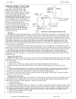
Rev. 9/25/2017
HDC-450, MANUAL
Copyright 2017 Vestil Manufacturing Corp. Page 11 of 26
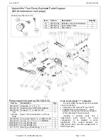
Detail view of items 9.1-9.3
“Autoshifter” Foot Pump Exploded Parts Diagram
[Bill of materials on next page]
9.1
9.2
9.3
Item Part no.
Description
Quantity
9.1
99-031-022 Release valve pin seal retainer
1
9.2
99-144-017 Seal, release valve
1
9.3
99-145-127 Star washer
1
Ports in pump body (“1” in diagram):
The auto-shifter foot pump has four possible
circuit connections.
2 pressure ports: marked “P” and “FC/P”;
2 intake/return ports: marked “T” - one is
located on the rear and the other is located
on the right side of the pump body.
Including 2 pressure ports and 2
intake/return ports allows the circuit
configuration to be adapted to varied
applications. The unused pressure and
intake/return ports are each plugged with an
SAE #6 port plug.
Pump repair kit (part no. 99-136-013)
Part no.
Description
Qty.
99-144-017 Polypack,
1
/
8
” x
3
/
8
” x
1
/
8
”
1
99-145-127 Retaining ring, STPA (star washer)
1
99-031-067 D-wiper,
1
1
/
4
” x 1.625 x 0.187
1
PP-
12501250
-
125B
Seal, 1.25 inner diameter x 0.125 cs
1
99-144-015 U-cup, twin lip rod,
3
/
4
” x 1.000 x 0.125
1
99-144-019 O-ring,
7
/
32
” x
11
/
32
” x
1
/
16
” 70D NBR
1
OR-904-N70 O-ring, #4 SAE port
3
OR-906-N70 O-ring, #6 SAE port
3
01-111-013 Bearing,
self-lubricating,
1
/
2
” x
1
/
2
”
2


