background image

Rev. 9/25/2017 


  HDC-450, MANUAL 

Copyright 2017 Vestil Manufacturing Corp.                                                                                     Page 25 of 26          


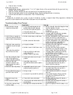
hh. Binding cylinders. 
ii.  Air present in the hydraulic system causing 
the velocity fuse to activate  

lowering solenoid valve from the block because the 
carriage will lower in an uncontrolled manner. 
hh

See 4 (r). 

ii

To unlock, pressurize the hydraulic system. 


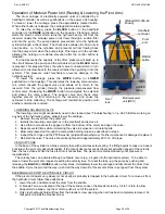
Labeling diagram:


Each unit should be labeled at all times as shown in the diagram below. Replace any label that is damaged and/or not 
easily readable. Numbers below label images in the diagram correspond to the identification number of each label. 


C: Label 287 (applied to upright frame member) 


A: Label 220 (applied to side of pivot arm) 


D: Label 206 (on base frame by oil reservoir 
or inside MPU on oil tank) 


Electric powered units also have the following labels applied to the modular power unit: 
 
HDC-DC: 


HDC-AC: 

D: label 206 is applied to metal frame inside MPU cover 


Label 295 (on MPU cover) 


B: Label 232 (applied to side of pivot arm) 


D: label 206 is applied to metal frame inside MPU cover 


Label 248; 249; 250; or 251 electrical system 
specifications 


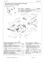
Summary of Contents for HDC-450 Series

Page 1: ...DC 450 84 Exploded Parts Diagram and Bill of Materials 7 8 HDC 450 96 Exploded Parts Diagram and Bill of Materials 8 9 Hydraulic System Foot Pump Standard Units Operation Purging Air from the Pump Pur...

Page 2: ...he drum handler The product is labeled with its capacity see Label 287 in Labeling diagram on p 25 Capacity is reduced to 500 pounds whenever a drum is half full or less Inspect the product as directe...

Page 3: ...1 16 493 16 547 8 453 4 1091 4 60 773 8 800 lb 364 kg 533 lb 243 kg HDC 450 72 91 11 16 41 11 16 49 3 16 54 7 8 45 3 4 109 1 4 72 92 1 2 800 lb 364 kg 535 lb 243 kg HDC 450 84 110 9 16 4511 16 533 16...

Page 4: ...Rev 9 25 2017 HDC 450 MANUAL Copyright 2017 Vestil Manufacturing Corp Page 4 of 26 HDC 450 60 Exploded Parts Diagram Bill of Materials on p 5...

Page 5: ...1 33 16 132 216 Caster wheel GFN 8 2 W 2 17 11129 Hex bolt gr A zinc finish 3 8 16x8 2 34 15 023 001 Reservoir non structural 1 HDC 450 60 Bill of Materials Exploded Parts Diagram on p 4 HDC 450 72 Bi...

Page 6: ...Rev 9 25 2017 HDC 450 MANUAL Copyright 2017 Vestil Manufacturing Corp Page 6 of 26 HDC 450 72 Exploded Parts Diagram Bill of Materials on p 5...

Page 7: ...Rev 9 25 2017 HDC 450 MANUAL Copyright 2017 Vestil Manufacturing Corp Page 7 of 26 HDC 450 84 Exploded Parts Diagram Bill of Materials on p 8...

Page 8: ...025 023 Handle grip 11 8 I D red 2 16 09 112 029 Pin clevis 2 32 09 516 004 001 Subassembly gear train pull chain 1 33 15 023 001 Reservoir 1 HDC 450 96 Exploded Parts Diagram Exploded Parts Diagram o...

Page 9: ...Rev 9 25 2017 HDC 450 MANUAL Copyright 2017 Vestil Manufacturing Corp Page 9 of 26 HDC 450 96 Exploded Parts Diagram Bill of Materials on p 8...

Page 10: ...s at a controlled rate Do not increase the pressure relief setting more than necessary i e be sure that you do not exceed the pressure rating of the components in the hydraulic system Purging Air from...

Page 11: ...n the rear and the other is located on the right side of the pump body Including 2 pressure ports and 2 intake return ports allows the circuit configuration to be adapted to varied applications The un...

Page 12: ...sure compensated 1 0 gal 1 7 99 114 001 Washer beveled spring washer 8 8 99 146 008 Spring relief 1 9 99 653 005 Assembly release valve packing 1 9 1 99 031 022 Accessory hydraulic relief valve pin se...

Page 13: ...ly OR I can pump the pedal but the arm does not move g Pump is air locked h Debris on seat of inlet check valve i Pressure setting of relief valve needs adjustment j Debris on seat of relief valve g R...

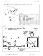
Page 14: ...her 1 9 15 533 013 Cable battery 23 black 1 10 15 533 014 Cable battery 23 red 1 11 23305 33688 33008 3 8 16 x 1 utility grade bolt 3 8 high collar lock washer 3 8 flat washer 2 2 2 12 99 135 011 4 12...

Page 15: ...Description Qty 31 568 015 BN70 O ring 1 32 568 011 BN70 O ring 1 33 99 153 058 Valve cartridge normally closed 1 34 99 034 010 Coil with weather tite plug 1 35 99 153 006 Valve pressure relief 1 36 5...

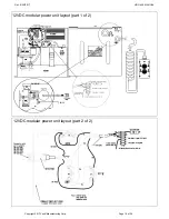
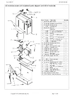
Page 16: ...Rev 9 25 2017 HDC 450 MANUAL Copyright 2017 Vestil Manufacturing Corp Page 16 of 26 12VDC modular power unit layout part 2 of 2 12VDC modular power unit layout part 1 of 2...

Page 17: ...688 33008 3 8 16 x 1 utility grade bolt 3 8 high collar lock washer 3 8 flat washer 2 2 2 12 01 627 010 Manifold see FIG 6C 1 13 01 143 906 Pump 1 14 HS52 Worm gear hose clamp 1 15 091802JY Fiberglass...

Page 18: ...enclosure plate 1 9 C500 3 8 1 2 knockout Romex 2 screw NM clamp connector 4 10 01 127 010 LHL standard manifold 3 boss 1 11 6801 06 06 NOW 3 8 16 x 1 utility grade bolt 2 12 99 153 011 Check valve 1...

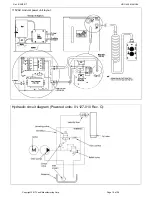
Page 19: ...Rev 9 25 2017 HDC 450 MANUAL Copyright 2017 Vestil Manufacturing Corp Page 19 of 26 Hydraulic circuit diagram Powered units 01 127 010 Rev C 115VAC modular power unit layout Cylinder...

Page 20: ...might occasionally need to be cleaned see Troubleshooting on p 24 25 Before working on any part of the hydraulic system always lower the carriage 1 Remove the cover from the power unit 2 Identify the...

Page 21: ...d electrical inlet The inlet projects through the cover housing of the power unit The user must provide a 3 prong charging cord appropriate for line and motor voltages The charger is current limited a...

Page 22: ...Hinged doors Gear handle Saddle in horizontal position 4 Lift the drum just a few inches above the ground using either the foot pump standard units or modular power unit HDC DC and HDC AC options Ins...

Page 23: ...nections 4 Frame elements inspect the legs vertical members and braces for cracked welds bends etc 5 Saddle drum retainer and pivot arm visually examine each element for damage Pay particular attentio...

Page 24: ...verloaded o Inoperative pump k Lower the carriage Remove the lowering solenoid valve and clean Refer to p 20 l Correct as appropriate See also 2 f h m See 1 b n See 2 e o See 2 j 4 Motor labors or is...

Page 25: ...el that is damaged and or not easily readable Numbers below label images in the diagram correspond to the identification number of each label C Label 287 applied to upright frame member A Label 220 ap...

Page 26: ...e warranty covers defects in the following original dynamic components motors hydraulic pumps electronic controllers switches and cylinders It also covers defects in original parts that wear under nor...

Reviews: