


19
Connecting the Water Supply
•
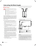
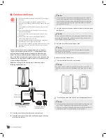
The following is a single water heater with storage back up for
small volume usage:
Ball valve
Circulation pump
Union
Check valve
Expansion tank
Pressure relief valve
Faucet
Hot
water
Cold water
Small
storage tank
AQUASTAT
•
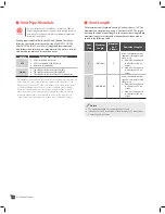
The following is a single water heater with storage back up for
large volume usage:
Ball valve
Circulation pump
Union
Check valve
Expansion tank
Pressure relief valve
Faucet
Hot
water
Cold water
Large
storage tank
AQUASTAT
Set the temperature 20°F lower than the
temperature set on the water heater.
Set the temperature 10°F lower
than the temperature set on the
water heater.
Pressure Relief Valve
Warning
Improper installation of the pressure relief valve may result
in property damage, personal injury, or death. Follow all
instructions and guidelines when installing the pressure relief
valve. Only a licensed professional should install the valve.
Caution
The pressure relief valve must conform to the current edition
of ANSI Z21.22 or CAN 1-4.4 and installation must follow local
codes.
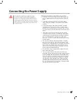
This water heater does not come with an approved pressure relief
valve. To complete the installation of the water heater, you must
install an approved 3/4", maximum 150 PSI pressure relief valve on
the pressure relief valve connector.
Pressure
relief valve
Notice
In recirculating system, install the pressure relief valve on the hot
water outlet. The pressure relief valve should be placed as close to the
water heater as possible. No other valve should be placed between the
pressure relief valve and the water heater.
When installing the valve, follow these guidelines:
•
Ensure that the discharge capacity of the pressure relief valve
is equal to or greater than the maximum pressure rating of the
water heater.
•
Ensure that the maximum BTU/H rating on the pressure relief
valve is equal to or greater than the maximum input BTU/H
rating of the water heater.
•
Direct the discharge piping of the pressure relief valve so that
hot water will not splash on any person or equipment near by.
•
Attach the discharge line to the pressure relief valve and run the
end of the line to within 6-12" (150-300mm) of the floor.
•
Ensure that the discharge line will allow free and complete
drainage with no restriction. Do not install a reducing coupling
or other restriction on the discharge line.
•
If the relief valve discharges periodically, this may be due to
thermal expansion in a closed water supply system. Contact the
water supplier or local plumbing inspector on how to correct
this situation. Do not plug the relief valve.
•
The pressure relief valve must be manually operated
periodically to check for correct operation.
Summary of Contents for VH-150
Page 46: ...Memo ...
Page 47: ...Memo ...


