Vertiv
™
|
Liebert
®
NX
™
225-600kVA Installation Manual | Rev. 8 | 07/2017
25
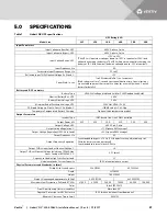
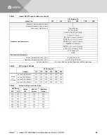
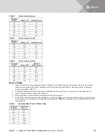
4.0
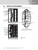
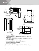
INSTALLATION DRAWINGS
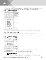
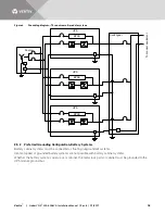
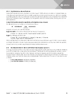
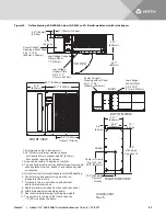
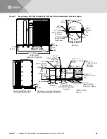
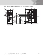
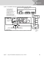
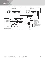
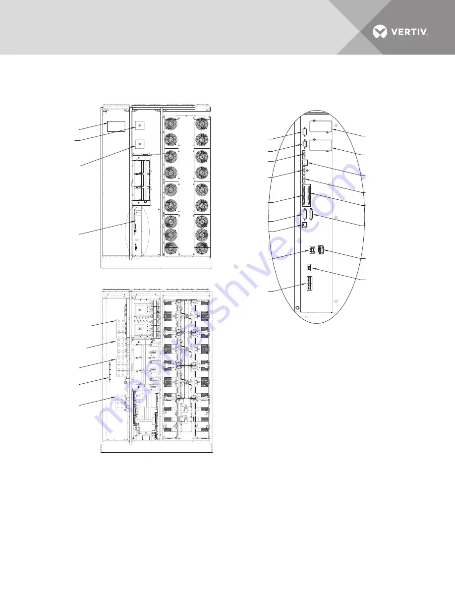
Figure 9
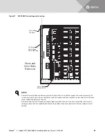
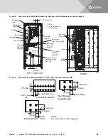
Main components, 225-300kVA Liebert NX UPS, SMS and 1+N multi-module unit with static bypass
Control LCD
Main Input
Circuit Breaker
(CB1), optional
Backfeed Circuit
Breaker (BFB)
External
Communication
Panel, See Detail A
Bypass Busbars
Ø, A, B, C
Rectifier Input
Busbars Ø, A, B, C
Input Ground
Busbar
Output Busbars
Ø, A, B, C
Battery
Busbars (+ /-)
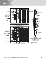
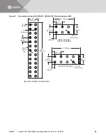
X3
X6
XT1/2
XT3/8
X19A
X20
XT2
(Non-Functional)
XS3
XS6 (LIFE)
X9
XT4
X19B
XT1
(Non-Functional)
XB4
TB2
TB3
TB1
Doors and Inner Skins Removed
Front Doors Removed
Detail A
External Communication Panel
(See specific control wiring drawings)
U38-3C-2000
Rev. 2


