


Vertiv
™
|
Liebert
®
NX
™
225-600kVA Installation Manual | Rev. 8 | 07/2017
6
1.4.4
Kick Plates and Floor Anchors for Special Seismic Certification—Optional
For seismic resistant installations and OSHPD compliance, special floor anchors and kickplates must be used for
the UPS and matching battery cabinets; see
Table 18
.
The California Office of Statewide Health Planning and Development (OSHPD) enforces International Building
Code requirements for Special Seismic Certification except that the office reduces the required scope of
certifications.
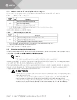
1.4.5
Kick Plate Installation—Standard
Kick plates must be installed. If the unit is to be installed in a position that does not permit access to rear kick
plates, then the kick plates must be installed before the unit is placed in its final position.
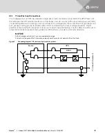
1.4.6
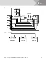
Special Considerations for 1+N Parallel Systems
Consider the grounding configuration of your system before finalizing module placement See
2.5 - Configuring
Ground Connections
.
Vertiv recommends matching the impedance in the bypass path of paralleled systems as closely as possible to
ensure good bypass current sharing.
The impedance mismatch can be minimized by controlling the wiring length of each unit. The design and the
layout of the UPS system and associated panels and cabling should be examined closely to ensure that cable
lengths and impedances are closely matched.
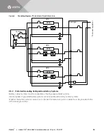
For Liebert NX Systems, the total combined cable length of the bypass feeder cables and the module output
cables for each module must be within 5% from maximum to minimum. The combined cable length is the sum of
the length from the common source feeding all the modules to the common output switchboard.
If the cabling impedances need to be greater than 5%, contact your Vertiv representative to calculate whether
the system will result in an overload condition when operating on bypass.
When bringing the 1+N system on-line for the first time or after removing one unit, Vertiv recommends checking
the bypass current mismatch. To check the bypass current mismatch:
1.
Place a load on the bypass of each UPS module.
2.
View the output current of each unit.
The accuracy of the currents displayed on the UPS module is sufficient for this check. If the mismatch is greater
than 5%, the bypass impedances must be balanced or the load must be limited to less than the maximum rating.
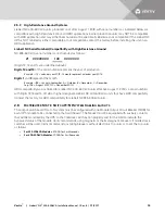
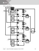
The output switchboard for any 1+N system must be configured with one Module Output Circuit Breaker (MOB)
for each UPS module that is to be connected to that switchboard. The breaker must be equipped with auxiliary
contacts that will be monitored by the UPS in order for interlocks to function properly and for the HMI to indicate
the bypassed status of the module.
Vertiv recommends using magnetic or thermomagnetic breakers. If molded case switches will be used, Vertiv
recommends installing breakers without electronic trip units or to set the trip units high enough to
accommodate high instantaneous currents that may be present when switching a module into an active bus.
For 225-250kVA Modules
—Set instantaneous trip settings to allow for 2000A for 2 milliseconds.
For 400-600kVA Modules
—Set instantaneous trip settings to accommodate 3000A for 2 milliseconds


