background image

Vertiv

|

Liebert

®

 NX

 225-600kVA Installation Manual | Rev. 8 | 07/2017

5

1.3.3

Installation Altitude

The maximum operating altitude of the UPS, without derating, is 3300ft. (1000m). At higher altitudes the load 
must be reduced according to 

Table 8

.

1.4

P

OSITIONING

The cabinet is structurally designed to handle lifting from the base.

Access to the power terminals, auxiliary terminal blocks and power switches is from the front.

The door can be opened to give access to the power connection bars, auxiliary terminal blocks and power 
isolators. The front door can be opened 90 degrees for more flexibility in installations.

1.4.1

Moving the Cabinets

The route to be traveled between the point of arrival and the unit’s position must be planned to make sure that 
all passages are wide enough for the unit and that floors are capable of supporting its weight (for instance, check 
that doorways, lifts, ramps, etc. are adequate and that there are no impassable corners or changes in the level of 
corridors).

Ensure that the UPS weight is within the designated surface weight loading (kg/cm

2

) of any handling equipment. 

For weight details, see 

Table 7

.

Move the UPS with a forklift or similar equipment to ease the relocation and to reduce vibration. The optional 
battery cabinets should be moved with a forklift or similar equipment.

When handling the UPS with a forklift or similar equipment, ensure any lifting equipment used in moving the UPS 
cabinet has sufficient lifting capacity. When moving the unit by forklift, care must be taken to protect the panels. 
Do not exceed a 15-degree tilt with the forklift. Bottom structure will support the unit only if the forks are 
completely beneath the unit.

Handling with straps is not authorized.

1.4.2

Clearances

The Liebert NX has no ventilation grilles at either side or at the rear of the UPS. Clearance around the front of the 
equipment should be sufficient to enable free passage of personnel with the doors fully opened. It is important to 
leave a distance of 24in (610mm) between the top of the UPS and any overhead obstacles to allow the module to 
be serviced and to permit adequate circulation of air coming out of the unit.

1.4.3

Raised-Floor Installations

If the equipment is to be located on a raised floor, it should be mounted on a pedestal suitably designed to 
accept the equipment point loading. Refer to the base view to design this pedestal.

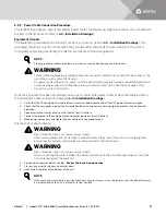
!

WARNING

Risk of heavy unit falling over. Improper handling can cause equipment damage, injury or death.
Because the weight distribution in the cabinet is uneven, use extreme care while handling and 
transporting. Take extreme care when handling UPS cabinets to avoid equipment damage or injury to 
personnel.
The UPS module weight is up to 4450 lb. (2019kg).
Locate center of gravity symbols and determine unit weight before handling each cabinet. Test lift and 
balance the cabinets before transporting. Maintain minimum tilt from vertical at all times.

Summary of Contents for Liebert NX 225 kVA

Page 1: ...Liebert NX UPS Installation Manual 225 600kVA 1 0PF 60Hz Three Phase Single Module Multi Module ...

Page 2: ...__________ Rating __________________________________________________________________________________________________________________ Date purchased _________________________________________________________________________________________________________ Date installed ___________________________________________________________________________________________________________ Location ______________...

Page 3: ... Devices 9 2 2 Power Cables 9 2 3 Sizing the Input Breaker Feeding a Liebert NX UPS 10 2 3 1 Single or Dual Input Feeds 10 2 3 2 Automatic Transfer Switches 10 2 3 3 Power Cable Connection Procedure 11 2 4 Control Cable and Communication 12 2 4 1 Slot for Liebert IntelliSlot or ManageUPS Communication Cards XS3 12 2 4 2 Slot for LIFE Services Products XS6 13 2 4 3 Serial Interface for Liebert LIFE...

Page 4: ...diagram Three wire multi module systems 18 Figure 5 System layout 1 N 20 Figure 6 SKRU connections 21 Figure 7 Control wiring 21 Figure 8 REPO connections 1 N system 22 Figure 9 Main components 225 300kVA Liebert NX UPS SMS and 1 N multi module unit with static bypass 25 Figure 10 Outline drawing 225 300kVA Liebert NX SMS and 1 N multi module unit with static bypass 26 Figure 11 225 300kVA low vol...

Page 5: ...e 4 Battery interface 15 Table 5 Maintenance bypass key status 16 Table 6 Maintenance Bypass SKRU Enable 16 Table 7 Liebert NX UPS specifications 37 Table 8 UPS rating at altitude 38 Table 9 Current ratings rectifier input 38 Table 10 Current ratings battery 39 Table 11 Recommended DC circuit breaker rating 39 Table 12 Current ratings bypass 39 Table 13 Current ratings output 39 Table 14 Current v...

Page 6: ...Vertiv Liebert NX 225 600kVA Installation Manual Rev 8 07 2017 iv ...

Page 7: ... dioxide fire extinguishers or those approved for use in fighting electrical fires Extreme caution is required when performing installation and maintenance Special safety precautions are required for procedures involving handling installation and maintenance of the UPS system Observe all safety precautions in this manual before handling or installing the UPS system Observe all precautions in the O...

Page 8: ...rue for oscilloscopes Always check with an AC and DC voltmeter to ensure safety before making contact or using tools Even when the power is turned Off dangerously high potential electric charges may exist at the capacitor banks and at the DC connections All wiring must be installed by a properly trained and qualified electrician All power and control wiring must comply with all applicable national...

Page 9: ...ally and externally Report any damage to the shipper immediately Verify that the correct equipment is being installed The equipment supplied has an identification tag on the interior doors reporting the type size and main calibration parameters of the UPS Verify that the UPS room satisfies the environmental conditions stipulated in the equipment specification paying particular attention to the amb...

Page 10: ...S modules are thoroughly inspected by Vertiv engineers prior to placement into service and testing on site However the person responsible for the site must ensure that the UPS module and the immediate surroundings are kept clean and free from any possible conductive material such as metal foil food wrappers cable shields washers and other hardware scrap metal and dust If the UPS system is shut dow...

Page 11: ...quipment ensure any lifting equipment used in moving the UPS cabinet has sufficient lifting capacity When moving the unit by forklift care must be taken to protect the panels Do not exceed a 15 degree tilt with the forklift Bottom structure will support the unit only if the forks are completely beneath the unit Handling with straps is not authorized 1 4 2 Clearances The Liebert NX has no ventilati...

Page 12: ...st be within 5 from maximum to minimum The combined cable length is the sum of the length from the common source feeding all the modules to the common output switchboard If the cabling impedances need to be greater than 5 contact your Vertiv representative to calculate whether the system will result in an overload condition when operating on bypass When bringing the 1 N system on line for the firs...

Page 13: ...f using a fork lift Do not remove the retaining brackets securing the UPS to the pallet because they are used to fasten the UPS to the floor except where OSHPD compliance is required and the optional OSHPD seismic anchoring kits are used Figure 1 Unpacking 1 5 SYSTEM COMPOSITION A UPS system can comprise a number of equipment cabinets depending on the individual system design requirements e g UPS ...

Page 14: ...e unit see the figures in 4 0 Installation Drawings Figure 2 Cabinet arrangement Liebert NX matching battery cabinets If the cabinets are to be bolted together the side panels must be removed before beginning Liebert NX UPS Liebert NX Battery Cabinet Liebert NX UPS Additional Liebert NX Battery Cabinets Battery Cabinets must be installed on left of UPS to wire internally ...

Page 15: ... Specifications When sizing battery cables a maximum volt drop of 2VDC is permissible at the current ratings given in Table 12 The following are guidelines only and are superseded by local regulations and codes of practice where applicable The grounding conductor should be sized according to the fault rating cable lengths type of protection etc The grounding cable connecting the UPS to the main gr...

Page 16: ...tive for more information The input current limit should not be set less than 105 of the current needed to support the inverter at full load for normal operation This results in sufficient power to recharge the battery in a reasonable time and to operate over the published input voltage range 2 3 1 Single or Dual Input Feeds The Liebert NX 225 600 kVA may be fed from single reference sources or du...

Page 17: ...nnections and tighten the connections to the proper torque Ensure correct phase rotation 6 For control connection details see 2 4 Control Cable and Communication 7 Close and secure the interior and exterior doors 8 Attach the kick plates to the bottom of the unit NOTE Proper grounding reduces problems in systems caused by electromagnetic interference WARNING Failure to follow adequate grounding pr...

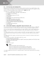
Page 18: ...external network interface for communication with network monitoring and building management systems Units built since June 2016 are equipped with either the Liebert IntelliSlot system or the ManageUPS system Previous units included a factory installed ManageUPS system which provided connectivity to SNMP and Modbus The Liebert IntelliSlot platform includes the Liebert IS UNITY DP and Liebert IS 48...

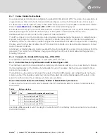
Page 19: ...Services or other special Liebert applications 2 4 4 Connector for REPO Input and Status XT3 8 This four pole screw connector allows Switching off the UPS from a remote source e g push button Providing status to an external system regarding whether the REPO is active To perform a remote emergency power off it is necessary to connect an emergency stop button to the UPS via a shielded cable not exce...

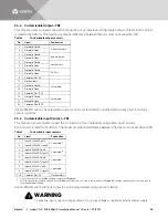
Page 20: ...ly Closed Alarm Summary 2 Normally Open 3 Normally Closed Bypass Active 4 Normally Open 5 Normally Closed Low Battery 6 Normally Open 7 Normally Closed AC Fail 8 Normally Open 9 Common Pins 1 8 10 Not Available 11 Normally Closed Selectable 12 Normally Open 13 Common Pins 11 12 14 Normally Closed Selectable 15 Normally Open 16 Common Pins 14 15 Table 3 Customizable input contacts Pin Signal Explan...

Page 21: ...rator mode is available that may be activated by a contact closure typically from the generator This mode shuts Off battery charging and brings the UPS out of Eco Mode while the generator is providing the power 2 4 8 Connector for Parallel UPS Connection X19A X19B This interface is used for paralleling two or more UPS s with each other 2 4 9 RJ 45 Interface for Synchronization with External Signal...

Page 22: ...y inserted 6 Key status switch common 7 Key status switch closed key removed 1 See 2 6 Distributed Static Switch 1 N System Cabling Layouts for 1 N systems with a Maintenance Bypass 2 Key Status Input must be Form C contact Table 6 Maintenance Bypass SKRU Enable Terminal Block Pin Description TB4 1 Maintenance Bypass Cabinet closed load not on inverter 2 Maintenance Bypass Cabinet common 3 Mainten...

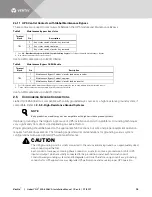
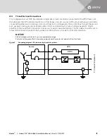
Page 23: ...ws through the ground path possibly tripping ground fault interrupters GFI s and distorting the output voltage waveform Proper adjustment of ground fault interrupters is necessary to avoid unwanted tripping The time delay should be set to at least 0 2 seconds to prevent tripping when the UPS performs a transfer or retransfer operation NOTICE Risk of improper installation Can cause equipment damage...

Page 24: ...Systems Battery cabinet systems must be connected as floating ungrounded systems Center tapped or grounded battery systems are not possible with battery cabinet systems Whether the battery system is open rack or cabinet the metal rack parts or cabinet must be grounded to the UPS module ground bus UPS Source G N BPSS G UPS BPSS G UPS BPSS G Switchgear To connect equipment G ...

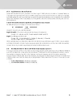
Page 25: ...anuary September A October B November C December e g 1 38 August 2013 1 3C December 2013 HRG compatibility was instituted for Liebert NX 400 600kVA units effective August 1 2013 so serial numbers with Digits 12 13 and 14 of 1 38 or higher designate Liebert NX 400 600kVA units that have HRG compatibility Contact the factory for HRG compatibility for Liebert NX 225 300kVA units 2 6 DISTRIBUTED STATI...

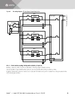
Page 26: ...7 3 4 1 2 1 2 REPO XT3 8 MBE TB4 Key Status TB3 MOB TB1 NC Com NO UPS 2 Output MBB TB1 Bypass REPO XT3 8 Input 1 2 1 2 1 2 3 5 6 7 3 4 MBE TB4 Key Status TB3 MOB TB1 NC Com NO UPS N See detail on SKRU Connection Page Output MBB TB1 Bypass REPO XT3 8 Input 1 2 1 2 1 2 3 5 6 7 3 4 MBE TB4 Key Status TB3 MOB TB1 NC Com NO REPO Switch Optional NC Com NO NC Com NO NC Com NO See detail on SKRU Connectio...

Page 27: ...itchgear or Panelboard Cabinet Powered from Critical Bus 1 120VAC Neutral 4 Transformer provided by others Fuse Fuse Fuse 6 14 12 11 9 8 Key Push Button for Key Release Contact position shown for key in captive position 7 10 13 Lamp 3 5 Auxiliary contacts from the SKRU must be isolated 3 6 5 8 9 11 12 14 13 10 7 1 4 1 2 3 5 6 7 1 2 3 1 2 3 5 6 7 5 6 7 UPS 1 X19 B X19 A UPS 2 X19 B X19 A UPS N X19 ...

Page 28: ... 07 2017 22 Figure 8 REPO connections 1 N system REPO XT3 8 1 2 REPO XT3 8 1 2 REPO XT3 8 1 2 UPS 1 Switchgear or Panelboard Cabinet 1 9 7 6 4 3 REPO Relay Contacts 8 5 2 All auxilliary contacts from the REPO must be isolated UPS 2 UPS N 1 3 4 6 7 9 2 5 8 ...

Page 29: ...inet MBD or BIS 3 1 5 Local EPO Button A local EPO button with protective cover is available This option is typically installed at the factory but may be field installed by Liebert Services 3 2 COMMUNICATION AND MONITORING Liebert IS UNITY DP card supports any two of the following BACnet IP BACnet MSTP Modbus RTU Modbus TCP and SNMP versions 1 2c and 3 Liebert IS 485 EXI card connects to Liebert S...

Page 30: ...lable At least one kit is required for each add on UPS module the number of kits required is one fewer than the number of UPS modules in the 1 N system e g six UPS modules would require five kits 3 3 2 Load Bus Sync Controller Distributes common reference synchronization signal for up to two Liebert NX 225 600 UPS modules A typical installation would have two modules synchronized to a common bypas...

Page 31: ...ional Backfeed Circuit Breaker BFB External Communication Panel See Detail A Bypass Busbars Ø A B C Rectifier Input Busbars Ø A B C Input Ground Busbar Output Busbars Ø A B C Battery Busbars X3 X6 XT1 2 XT3 8 X19A X20 XT2 Non Functional XS3 XS6 LIFE X9 XT4 X19B XT1 Non Functional XB4 TB2 TB3 TB1 Doors and Inner Skins Removed Front Doors Removed Detail A External Communication Panel See specific co...

Page 32: ...un in separate cable entry 7 All wiring is to be in accordance with national and local electrical codes 8 Depth dimension includes front door and rear panel 9 Width dimensions include side panels 10 See technical data drawing for shipping weights 11 The height is to the top of the frame fans rise 1 5 38 1mm above the frame 76 8 1950mm See Note 12 FRONT FRONT FRONT VIEW RIGHT SIDE VIEW BOTTOM VIEW ...

Page 33: ...e conduit holes land the conduit and then route the control wire to the chimney stack toward the bottom of the unit Run the control wires to through the conduit plate provided If the unit is not on a raised floor then insert a rubber grommet into the conduit plate hole at the bottom of the entry location for the low voltage control wiring Low Voltage Top Entry Low Voltage Bottom Entry Doors and In...

Page 34: ...1 5 546mm 15 6 x 1 1 397 x 27mm Pad See Detail A BOTTOM VIEW FOOTPRINT SPACING Top View 11 5 291mm 0 4 11 Door 0 1 2mm Pad to Outside End Panel 1 1 27mm Pad to Outside Door Panel DETAIL A Pad Pad FRONT VIEW WITHOUT KICKPLATE 2 2 56mm 53 1 1350mm 48 7 1238mm 31 5 800mm 27 6 700mm 1 8 47mm Unit bottom is structurally adequate for forklift handling front or rear only 4 1 103mm Leg 1 7 42mm RIGHT ISOM...

Page 35: ...ypass Input ØC Bypass Input ØC Input ØB Input ØA Input Ground FRONT LEFT SIDE VIEW ØA Output See Bus Dwg 356 ØB Output See Bus Dwg 372 ØC Output See Bus Dwg 356 See Bus Dwg 356 Ground See Bus Dwg 349 Batt Customer Busbar See Bus Dwg 370 See Bus Dwg 372 Ø 0 6 15mm 3 1 78 7mm Typ 4 8 122mm NOTE See individual bus detail drawings 1 18 30mm Typ 0 59 15mm Typ Connection Busbar 0 63 16mm Battery Busbar ...

Page 36: ...ed Circuit Breaker BFB External Communication Panel See Detail A Bypass Busbars Ø A B C Rectifier Input Busbars Ø A B C Input Ground Busbar Output Busbars Ø A B C Battery Busbars X3 XS3 X6 XT1 2 XT3 8 X19A X20 X9 XT4 X19B XT1 Non Functional XT2 Non Functional XS6 LIFE TB2 TB3 TB4 TB1 Doors and Inner Skins Removed Front Doors Removed Detail A External Communication Panel See specific control wiring...

Page 37: ...local electrical codes 8 Depth dimension includes front door and rear panel 10 Width dimensions include side panels 11 See technical data drawing for shipping weights 11 The height is to the top of the frame fans rise 1 5 38 mm above the frame 33 7 856mm 33 7 856mm 29 8 756mm 1 5 38mm 2 4 62mm 34 7 881mm 19 3 489mm Center of Gravity 40 2 1022mm Center of Gravity Center of Gravity Typ for Front 36 ...

Page 38: ...Leg 1 7 42mm Pad Pad 2 2 56mm 2 2 x 2 56mm x 50mm Pad Typ Opposite Side 4 4 x 2 112mm x 50mm Pad Typ Opposite Side 2 2 x 2 56mm x 50mm Pad Typ 4 Corners 23 5 x 1 1 597mm x 27mm Pad 1 1 27mm Pad to Outside Door Panel 0 1 2mm Pad to Outside End Panel 86 1 2188mm 90 6 2300mm Rail See Detail A FRONT 21 5 x 5 547mm x 13mm Pad 1 1 x 2 28mm x 50mm Pad Typ 2 Places 10 5 266mm 10 7 271mm 1 3 34mm 14 4 366m...

Page 39: ...N multi module unit with static bypass Battery Customer Busbar FRONT Ground ØB Output ØC Output ØA Output ØA Input ØB Input ØC Input ØC Bypass Input ØB Bypass Input ØA Bypass Input FRONT 78 3 1990mm 12 9 326mm LEFT SIDE VIEW 3 1 v 80mm Typ 25 8 656mm 32 1 814mm 38 3 972mm 44 5 1130mm 50 7 1288mm 57 1448mm 4 7 120mm 90 7 2304 ...

Page 40: ...ert NX 400kVA 600kVA UPS 1 N multi module or SMS INPUT BYPASS OUTPUT BUSBAR 3 2 80 3mm GROUND CONNECTION BUSBAR 18 1 460mm Ø 0 6 15mm Typ Ø 0 6 15mm Typ Ø 0 6 15mm Typ 1 4 35mm BATTERY BUSBAR 9 2 233mm 2 50mm 2 50mm 3 1 80mm 3 1 80mm 1 25mm 1 25mm 6 8 173mm 0 7 18mm 1 8 44 5mm 1 8 44 5mm 1 8 44 5mm ...

Page 41: ...ource MBB MIB Critical Load MAINTENANCE BYPASS SWITCHBOARD UPS System Source ECO Mode Enabled On Disabled Off 1 Key release unit with associated controls and locking devices supplied by switchboard provider 2 Switchboard gear manufacturer to provide all wires pins sockets connectors and proper designation as shown 3 All wiring to be UL CSA approved 4 Wire gauge to be 16 AWG minimum except where no...

Page 42: ...sition with key installed 6 L X X X Maintenance Bypass Source MBB MIB Critical Load MAINTENANCE BYPASS SWITCHBOARD UPS System Source ECO Mode Enabled On Disabled Off 1 Key release unit with associated controls and locking devices supplied by switchboard provider 2 Switchboard gear manufacturer to provide all wires pins sockets connectors and proper designation as shown 3 All wiring to be UL CSA ap...

Page 43: ... for VRLA FLA DC Ripple Voltage in Float Const V Ch Mode 1 RMS value 3 4 Vpp Temperature Compensated Battery Charging Optional with temperature probe Output Parameters Inverter Type IGBT based Sine Sine PWM Controlled Output Power kW 225 250 300 400 500 600 Output Voltage VAC 480V 3 ph 3 wire Output Voltage Regulation 1 3 phase RMS average Output Voltage Regulation 100 Unb Load 2 3 phase RMS avera...

Page 44: ...25 to 70 Operating Temperature Range F C 32 to 104 0 to 40 UPS Relative Humidity 95 or less Non Condensing Operating and Non Operating Table 8 UPS rating at altitude Altitude UPS Rating kW 225 250 300 400 500 600 Rating vs Altitude up to 3300ft 1000m 225 250 300 400 500 600 up to 4921ft 1500m 225 250 270 400 500 540 up to 6562ft 2000m 225 250 252 400 500 504 up to 9842ft 3000m 225 225 225 400 450 ...

Page 45: ...tective Device Caution To reduce the risk of fire connect only to a circuit with the maximum branch circuit overcurrent protection recommended in Table 13 in accordance with the National Electric Code ANSI NFPA 70 Table 10 Current ratings bypass UPS Rating kVA kW Voltage VAC Nominal Current 225 480 271 250 480 301 300 480 361 400 480 481 500 480 601 600 480 722 Table 11 Current ratings output UPS ...

Page 46: ... 2 733 3 12 2 916 7 15 3 1100 0 18 3 1100 0 18 3 120 412 5 6 9 550 0 9 2 687 5 11 5 825 0 13 8 825 0 13 8 125 319 4 5 3 425 9 7 532 4 8 9 638 9 10 6 638 9 10 6 130 222 2 3 7 296 3 4 9 370 3 6 2 444 4 74 444 4 74 135 152 7 2 5 203 6 3 4 254 6 4 2 305 5 5 305 5 5 140 100 6 1 7 134 2 2 2 167 7 2 8 201 3 3 4 201 3 3 4 145 36 7 48 9 61 1 1 0 73 3 1 2 73 3 1 2 150 27 7 37 0 46 2 55 4 55 4 155 7 3 9 7 12...

Page 47: ...C 3 750kcmil 3 0AWG 600 600 480 2 3 0C 3 750kcmil 1 0AWG 3 2 5C 3 500kcmil 3 0AWG Output UPS Rating Voltage VAC of conduits size of conduits size of phase cables per conduit size of cable for ground per conduit kVA kW Copper Conductors Aluminum Conductors 225 225 480 1 2 5C 3 500kcmil 4AWG 1 2 5C 3 600kcmil 2AWG 250 250 480 1 2 5C 3 500kcmil 3AWG 1 3 0C 3 750kcmil 1AWG 300 300 480 2 1 5C 3 4 0AWG ...

Page 48: ...400kcmil 54916BE 54874BE 60168 60269 500kcmil 54918BE 54876BE 60171 60273 600kcmil 54920BE 54878BE 60176 60275 750kcmil 54922BE 54880BE 60178 60277 Table 17 Recommended torque values Grade 5 Steel Unified Thread System Torque lbf in Class 8 8 Steel Metric Thread System Torque N m Fastener Finish Plain Steel Zinc Plating Fastener Finish Plain Steel Zinc Plating Size Threads Inch Tpi No Washer Flat ...

Page 49: ...r NX 300 kVA UPS Module NXOSH600 OSHPD Floor Anchor NX 600 kVA Module NXOSHFTBC OSHPD Floor Anchor NX Front Terminal Battery Cabinet NXOSHTTBC OSHPD Floor Anchor NX Top Terminal Battery Cabinet NXOSHNJC OSHPD Floor Anchor NX Top Terminal Battery 393mm Junction Cabinet NXOSHPJC OSHPD Floor Anchor NX Front Terminal Battery 393mm Junction Cabinet NXOSHWJC OSHPD Floor NX 785mm Junction Cabinet ...

Page 50: ...Vertiv Liebert NX 225 600kVA Installation Manual Rev 8 07 2017 44 Notes ...

Page 51: ... 800 543 2378 Outside North America 614 841 6598 LOCATIONS United States 1050 Dearborn Drive P O Box 29186 Columbus OH 43229 Europe Via Leonardo Da Vinci 8 Zona Industriale Tognana 35028 Piove Di Sacco PD Italy 39 049 9719 111 Fax 39 049 5841 257 Asia 29 F The Orient Square Building F Ortigas Jr Road Ortigas Center Pasig City 1605 Philippines 63 2 687 6615 Fax 63 2 730 9572 ...

Page 52: ...d completeness herein Vertiv Co assumes no responsibility and disclaims all liability for damages resulting from use of this information or for any errors or omissions Specifications are subject to change without notice This document may contain confidential and or proprietary information of Liebert Corporation and its receipt or possession does not convey any right to reproduce disclose its conte...

Reviews: