background image

Vertiv

| Liebert

®

 ITA2

 User Manual  | 

60

APPENDIX A - UPS PROMPTS AND ALARMS

A.1

Prompt Window

A prompt window is displayed during the operation of the system to alert you to certain 
conditions and/or to require confirmation of a command or other operation. 

Table 16

 lists the 

prompts and meanings.

A.2

UPS Alarm Message List

Table 17

 lists all UPS alarm messages based on the 

Current

 and 

History

 menus.

Table 16

UPS prompts and meanings

Prompt

Meaning

System setting is different, please 
check

Appears when the parallel parameters are different.

Cannot set this on-line, please shut 
down output

If the user wants to change some important settings under condition of output 
(output voltage, output frequency, output phase No.), the prompt will appear

Incorrect password, please input 
again

Appears when the user incorrectly inputs the Settings password

Operation failed, condition is not 
met

Appears when the user wants to execute a certain operation but conditions are not 
met

Password changed OK

Appears when the user successfully change the Settings password

Fail to change password, please try 
again

Appears when the user tries to change the Settings password but input two different 
new passwords

The time cannot be earlier than 
system time

Appears when the user sets the time of 'Turn on delay' or 'Turn off delay' is earlier 
than the current system time.

Turn on failed, condition is not met

When users press the power button (or execute the command of 'Turn on/Turn off/to 
Bypass' under 'Control' Screen), the prompt will appear

Please disconnect power, check 
output: 1 phase, 3 phase, then 
power UPS On

Appears when the output phase is changed. The system requires the user to power 
Off and check the cable connections, then power On the UPS again to guarantee the 
safety.

Table 17

UPS alarm messages

Alarm message

Description

Communication fail

Internal communication is abnormal; verify that the communication cables are connected 
correctly.

Rectifier fault

A rectifier fault has been detected.

DC/DC fault

The battery charger has a fault.

DC bus abnormal

The DC bus has a fault. The load will transfer to bypass if the bypass is available.

Charger fault

The charger output voltage is abnormal, and the charger is Off.

Aux. power fault

The auxiliary power output voltage exceeds the normal range.

Input back-feed

A rectifier short circuit is detected while in Battery Mode.

Inverter fault

The inverter is Off when the inverter output voltage and current exceed the setting range. 
If bypass is available, the UPS will transfer to bypass mode, otherwise the system will 
power Off.

Output short

Check that the output cables are not shorted.

Bypass backfeed

A bypass short circuit is detected while in Battery mode.

Output off, voltage is not zero

When there is no output, the system detects that the output has a voltage.

Summary of Contents for Liebert ITA2-08KRT208

Page 1: ...Liebert ITA2 8 10kVA 60Hz 208 220V Three Phase UPS User Manual...

Page 2: ...r damages resulting from use of this information or for any errors or omissions Refer to other local practices or building codes as applicable for the correct methods tools and materials to be used in...

Page 3: ...Operation Mode 6 1 5 1 Normal Mode 6 1 5 2 Bypass Mode 7 1 5 3 Battery Mode 7 1 5 4 Auto Restart Mode 8 1 5 5 Eco Mode Single UPS 8 1 5 6 Fault State 8 1 5 7 Maintenance Bypass Mode 9 2 0 SINGLE UPS...

Page 4: ...sfer Between Operation Modes 43 4 2 1 Transfer from Inverter Mode to Bypass Mode 43 4 2 2 Transfer From Bypass Mode to Inverter Mode 44 4 3 REPO 45 5 0 COMMUNICATION 46 5 1 Liebert IntelliSlot Port 46...

Page 5: ...ure 20 Wiring diagram Single input configuration 20 Figure 21 Wiring diagram Dual input configuration 21 Figure 22 Battery insulating plate 22 Figure 23 Cables between Liebert ITA2 and battery cabinet...

Page 6: ...Pin layout of dry contact ports 47 Figure 58 REPO cable connections 48 Figure 59 Battery cabinet 51 TABLES Table 1 Model configurations 3 Table 2 Currents and wire size UPS rectifier input single sour...

Page 7: ...ntenance of the UPS system Observe all safety precautions in this manual before handling or installing the UPS system Observe all precautions in this manual before as well as during performance of all...

Page 8: ...erials sold hereunder cannot be used in the patient vicinity e g use where UL cUL or IEC 60601 1 is required Medical applications such as invasive procedures and electrical life support equipment are...

Page 9: ...lized collection and disposal centers If this unit must be dismantled this must be done by a specialized center for collection and disposal of electric and electrical appliances or other dangerous sub...

Page 10: ...Tower installation and rack installation meet different installation requirements Parallel connection capability to achieve up to 1 1 parallel redundant power High frequency double conversion topolog...

Page 11: ...ation and display panel LED indicators and function keys Figure 1 UPS front panel 1 3 2 Components Rear Panel As shown in Figure 2 the UPS rear panel features parallel LBS ports dry contact port I O t...

Page 12: ...roper service Can cause property damage injury or death The Liebert ITA2 has no user serviceable parts Contact Vertiv Support at 800 548 2378 in the event of any malfunction that requires service Unau...

Page 13: ...precise regulated AC output power 1 4 4 DC DC Charger Whenever the Liebert ITA2 is connected to utility power and the rectifier is operating the battery charger receives energy through the internal DC...

Page 14: ...nditioned sine wave power when the utility input is normal In Normal Mode the battery charger will operate charging the battery The run indicator green will be On the alarm indicator will be Off and t...

Page 15: ...e NOTICE Risk of power interruption Can damage the connected load In case of utility failure or utility voltage out of range in Bypass Mode the UPS will shut down and shut Off the output power to the...

Page 16: ...6 Fault State In Normal Mode the UPS will transfer to Bypass Mode if the inverter fails or if UPS overtemperature occurs In Battery Mode with no bypass utility the UPS will shut down and stop output...

Page 17: ...available at Vertiv s Web site www vertivco com Figure 7 Maintenance Bypass Mode NOTE The Liebert ITA2 has no user serviceable parts If the UPS malfunctions and requires service contact Vertiv Suppor...

Page 18: ...pright 2 Open the carton and remove the packing 3 Lift out the accessories and set them aside 4 Lift the UPS out of the box and stand it or lay it aside 5 Remove the UPS as shown in Figure 8 WARNING R...

Page 19: ...s against the delivery list If any problem is found notify your local Vertiv representative immediately 2 2 Moving the UPS The UPS cabinet can be moved manually by an adequate number of personnel or w...

Page 20: ...hown in Table 15 2 3 2 Environmental Requirements UPS Room The UPS is designed for indoor installation in a clean well ventilated environment with the ambient temperature within the specifications sho...

Page 21: ...2 4 External Protective Devices A circuit breaker or other protective devices must be installed at the external AC input end of the UPS This section provides general guidance for installation by a pr...

Page 22: ...current fed by the RFI filter in the UPS ranges from 3 5mA to 100mA Vertiv recommends verifying the sensitivity of each differential device of the upstream input power distribution and downstream powe...

Page 23: ...as shown in Figure 12 Figure 12 Assemble the support base for UPS and battery cabinets 4 Place the UPS on the support bases and support base extensions as shown in Figure 13 Figure 13 UPS and battery...

Page 24: ...ght guide rail guide rail screws and panel screws from the package distinguish the left guide rail and right guide rail according to Figure 15 and confirm its retractable function Figure 15 Guide rail...

Page 25: ...screws to mount the UPS in the rack through the brackets as shown in Figure 18 NOTE The guide rail holder must be nearer the front of the rack Each end of a guide rail has four installation holes see...

Page 26: ...an the Liebert ITA2 UPS Vertiv recommends installing the battery cabinets as near the bottom of the rack as possible to maintain a low center of gravity Install the UPS above the battery cabinets Each...

Page 27: ...G 10AWG Input sizes and values apply to dual source configuration Table 4 Ring terminal part numbers AWG mm2 10 5 26 8 8 36 6 13 3 Part McMaster Carr 7113K462 McMaster Carr 7113K444 McMaster Carr 7113...

Page 28: ...e from the upstream feeder panel to UPS Jumper 11 Phase B cable from the upstream feeder panel to UPS Jumper 12 Phase C from the upstream feeder panel to UPS Terminal 13 Neutral from the upstream feed...

Page 29: ...ox cover and secure it Figure 20 Wiring diagram Single input configuration 2 6 3 Dual Input Configuration Dual input configuration for the UPS requires that both feeds be from the same source 1 PE Out...

Page 30: ...l to UPS Terminal 12 Phase B cable from the upstream feeder panel to UPS Terminal 14 Phase C from the upstream feeder panel to UPS Terminal 16 Neutral from the upstream feeder panel to UPS Terminal 18...

Page 31: ...le to the battery terminals as shown in Figure 22 1 PE Output PE Terminal 2 C AC Output Terminal Phase C 3 B AC Output Terminal Phase B 4 A AC Output Terminal Phase A 5 N Output Neutral Line Terminal...

Page 32: ...iv Services at 800 543 2378 2 Maintain at least 10mm clearances between the front rear side panels of the battery and the wall or adjacent equipment to keep well ventilated 3 Maintain some clearances...

Page 33: ...ing will connect to Terminal A of the second string Figure 23 Cables between Liebert ITA2 and battery cabinets The cable connections between the battery cabinet and the UPS are shown in Figure 24 1 Co...

Page 34: ...A Battery Cabinet 1 7 Terminal B Battery Cabinet 1 8 Terminal A Battery Cabinet 2 9 Terminal B Battery Cabinet 2 10 Terminal A Battery Cabinet 3 11 Terminal A Battery Cabinet 4 12 Communication Port 1...

Page 35: ...the UPS unit The panel has an On Off button four menu navigation buttons two LED indicators and a liquid crystal display LCD as shown in Figure 25 Figure 25 Operation and display panel 1 LCD 2 Run Ind...

Page 36: ...ello w On Alarm occurs Red On Fault occurs N A Off No alarm no fault Table 7 Audible alarm description Sound Meaning Continuous beep Generated when a UPS fault appears such as a fuse or hardware failu...

Page 37: ...rent and past alarms and stored events 3 2 LCD Menu Structure Figure 27 LCD menu structure 1 2 3 4 1 Eco Mode 2 Programmabl e Output 3 Ambient Temperature Humidity displayed only when sensor is connec...

Page 38: ...igure 28 Start screen 3 3 2 UPS Mimic Screen After the system test the UPS Mimic shown in Figure 29 will appear The UPS Mimic page shows the UPS status including input bypass rectifier battery inverte...

Page 39: ...ters and item settings After entering the submenu screen if there is a tab control move the cursor to the tab At this time you can press the or key to switch the tab Press the key to move the cursor t...

Page 40: ...Vertiv Liebert ITA2 User Manual 34 Figure 31 Status page menus...

Page 41: ...see Figure 32 For details about the parameters setting refer to 3 6 1 LCD Parameter Settings Figure 32 Settings Page password Figure 33 Settings Page menus NOTE The default password 111111 must be ent...

Page 42: ...Vertiv Liebert ITA2 User Manual 36 Figure 34 Settings Page menus continued Monitor Pg 2 System Pg 2...

Page 43: ...ual 37 Control Page The Control page shows Turn ON OFF to BYPASS and Manual battery test etc See below Figure 35 Control page menus Log Screen The Log Screen contains the Current and History See below...

Page 44: ...ut Screen shows information about Product and Network See below Figure 37 About Screen menus Maintain Screen Figure 38 Maintain Screen Password required NOTE The Maintain Screen is protected with a pa...

Page 45: ...ey to highlight it then press the Enter key to confirm the choice The LCD will display elements in the designated language 6 Press the key several times to return to the main menu 3 5 Changing Current...

Page 46: ...rd 1 At the main menu screen press the or key to select Settings See Figure 43 2 Press the Enter key the interface shown in Figure 41 will appear 3 Enter the password and press OK Figure 41 Entering p...

Page 47: ...tings 8 After entering the new password press the Enter key to confirm it The system requires confirming the new password see Figure 44 9 Re enter the new password Figure 44 Confirm new password 10 Af...

Page 48: ...ttings Menu Item Setting Range Default Setting Syste m Auto restart Disable Enable Enable Auto restart delay 0 999 seconds 10 Single unit only Guaranteed shutdown Disable Enable Disable Remote control...

Page 49: ...ction Auto BypEna Auto BypDisa 50Hz BypDisa 60Hz BypDisa Auto BypEna Run mode Normal ECO mode Normal Redundant NO YES YES System parallel No 1 2 1 Sync parallel parameters By HMI Interface Button N A...

Page 50: ...Turn on when power returns for 0 4320 min 0 Monit or Language English Chinese Spanish French English Date YYYY MM DD 2016 10 01 Time HH MM SS 00 00 00 Display orientation Auto Rotate Horizontal Vertic...

Page 51: ...operation if there is no alarm or user interaction within two minutes the default screen shown in Figure 46 will appear At the default screen if there is an alarm or a fault or if the user presses an...

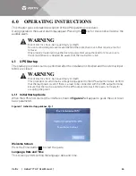
Page 52: ...nter button to start the guide Language Date and Time This screen permits setting the language date and time WARNING Risk of electric shock Can cause injury or death No user accessible parts are locat...

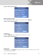
Page 53: ...es The default is 32 See Figure 49 Figure 49 Initial startup guidance Pg 3 Output Screen As shown in Figure 50 output voltage and output frequency can be set Figure 50 Initial startup guidance Pg 4 Fi...

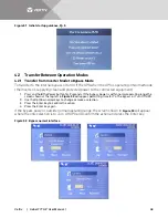
Page 54: ...hold the Power button for 2 seconds If the bypass power is within normal operating range the screen shown at the top left in Figure 52 will appear permitting transfer To The Bypass or Turn Off UPS 2 U...

Page 55: ...wn in Figure 54 will appear with the choice of Turn On UPS or Turn Off UPS 2 Use the Up Down arrow keys to change or make the selection 3 Press the Enter key 4 Confirm the action and press the Enter k...

Page 56: ...ency Power Off REPO connector for either Normally Open N O or Normally Closed N C systems An interface with the REPO circuit must be field supplied to allow disconnecting the UPS input feeder breaker...

Page 57: ...all protocols are available at the same time Refer to the relevant user manual for the installation and operation guide The manual ships with the card and is available at Vertiv s Web site www vertiv...

Page 58: ...4 GND Ground 3 Input Port 1 5 Battery Mode shutdown Any mode shutdown Remote Comms Shutdown Maintain mode Default Maintain Mode can be set via the LCD Settings Screen When Pin 5 and Pin 6 are shorted...

Page 59: ...end of the DB 9 serial port communication cable to the DB 9 serial port see Port 5 in Figure 2 on the rear panel of the UPS connect the other end to the computer s DB 9 port NOTE Vertiv recommends us...

Page 60: ...he standard RJ 45 port which supports the Modbus Jbus port and connects the Vertiv temperature temperature and humidity sensor The user can select Modbus Jbus protocol function or sensor function via...

Page 61: ...sult in serious environment pollution and violates national and local laws Vertiv has a service network and recycle system to assist users to deal with the waste battery by law Contact Vertiv Services...

Page 62: ...able that was supplied with the UPS for UPS to Battery cabinet connections 1 meter long ITA2 BCI20K02L4 UPS to Battery Cable Kit 2 meters long ITA2 BCI20K02L2 Battery to Battery Cable Kit 1 meter long...

Page 63: ...0 7 2k W 6 48k W 5 76k W 5 4k W 5 04k W 4 32k W 3 6k W 2 88k W 2 16k W 1 8k W 1 44k W 0 72k W 1 13 15 18 19 21 26 33 40 56 75 101 166 2 33 36 40 45 49 61 76 102 135 151 167 345 3 52 61 71 77 82 103 12...

Page 64: ...p to 93 4 Battery Type Sealed Lead Acid Maintenance Free Number of Cells 192 by Default Rated Voltage VDC 384 Charge Current Maximum A 1 8 3 5 Transfer Time Utility to Battery ms 0 0 Inverter to Bypas...

Page 65: ...Vertiv Liebert ITA2 User Manual 59 Weight lb kg Net 50 7 23 Shipping 70 5 32 Table 15 Specifications Item Description 8kVA 10kVA...

Page 66: ...off delay is earlier than the current system time Turn on failed condition is not met When users press the power button or execute the command of Turn on Turn off to Bypass under Control Screen the p...

Page 67: ...e user can set the time ranging from 2min 30min 2 min by default Please shut down the load timely Battery voltage abnormal When battery is connected the system checks that the battery voltage exceeds...

Page 68: ...cables connection are shorted with the enclosure On maintenance bypass The dry contact in maintenance bypass state is activated Battery mode The UPS is on battery and the inverter starts Bypass mode T...

Page 69: ...Sync parallel parameters command to activate the event Local settings sync OK Local parameters are successfully synchronized System settings sync OK All the parameters are successfully synchronized L...

Page 70: ...Vertiv Liebert ITA2 User Manual 64 NOTES...

Page 71: ...Vertiv Liebert ITA2 User Manual 65...

Page 72: ...Vertiv Liebert ITA2 User Manual 66...

Page 73: ......

Page 74: ...mes and logos referred to are trade names trademarks or registered trademarks of their respective owners While every precaution has been taken to ensure accuracy and completeness herein Vertiv Co assu...

Reviews: