5
vertilux.com
© 2019. Vertilux, Ltd. All Rights Reserved. Last revised: February 2019.
TRAVERSING MOTOR
RED BUTTON
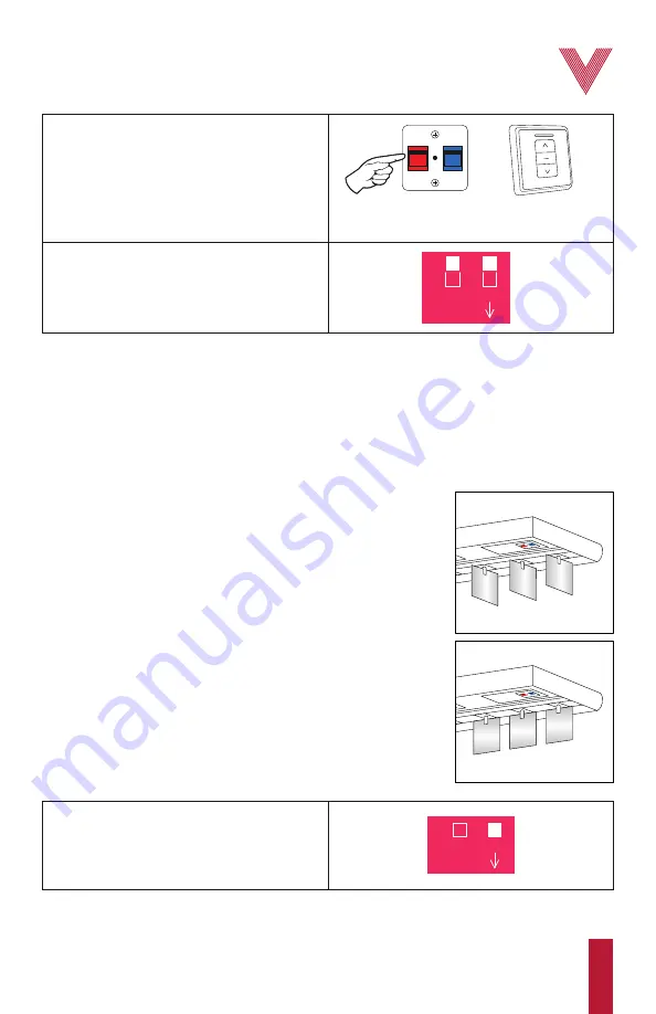
8.
You can now release the
red button
.
On the wall control, press the same
direction
button
as selected in step 3.
The other traversing limit has now been set.
DIRECTION BUTTON
9.
Set all DIP switches in the
OFF
position and
proceed with the setting of the tilting limits. If the
tilting limits are already set, place DIP switch
No. 4
in the
OFF
position and
No. 2
in the
ON
position. Both motors’ limits are now set.
1
DIP ON
2 3 4
1.
To set the tilting limits, set only DIP switch
No. 4
in the
ON
position.
1
DIP ON
2 3 4
Setting tilting limits
Before starting...
To set the tilting limits, the
2 buttons (red and blue)
must be
unlocked. The buttons are unlocked when they “click” once pressed.
If either button is locked, follow the procedure on
pages 8-9
to reset
the motor to factory default settings.
The carriers must be spread out to approximately the middle of the
track so that not all the slats are stacked to one side. If the
traversing limits are already set, put the DIP switch
No. 2
and
No. 4
in the
ON
position. Using the wall control, move the slats to the
middle of the track, approximately.
The carriers must be aligned and set to 90° of the track in the
“open” position
(fig. 4)
. To do this, remove the track
COVER
, remove
GEARS
1
,
2
and
3
, and rotate manually
GEAR 4
until the carriers are
aligned and set to 90° of the track. Then place the
GEARS
back
(fig. 3)
.
Insert a piece of slat or a small card in one of the carriers in order to
set the tilting limits precisely. After aligning the carriers, re-asemble
the motor.
*If you made a mistake and pressed the stop button when the carriers were not in the desired
position, you can readjust their position with the direction buttons as long as you don’t release the
button that you have pressed on the motor.
Fig. 5
. Slats in 0º
Fig. 4
. Slats in 90º
IMPORTANT:
Secure the motor settings by covering the
limit setting buttons
with their cover.
Summary of Contents for VTi 6-710-VB-00110
Page 20: ......


