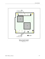
Physical Details
EPM-32 Reference Manual
13
H
ARDWARE
A
SSEMBLY
The EPM-32 consists of two boards that are mounted together with four 5mm x 15mm M3
threaded hex male/female standoffs (p/n VL-HDW-101) using the corner mounting holes. These
standoffs are secured to the top circuit board using four pan head screws.
Caution:
Extreme care must be taken not to damage components near the corner mounting
holes when tightening standoffs with nut driver tools.
Additional PC/104-
Plus
or PC/104 cards can be attached to the bottom of the EPM-32 board set
and secured with standoffs or 5mm nuts.
PC/104-
Plus
expansion modules can be secured directly to the underside of the EPM-32.
PC/104 expansion modules can be secured to the underside of the EPM-32; however, the 40-pin
and 64-pin ISA pass-through connectors may need to be extended, and longer standoffs might
need to be used to provide adequate clearance between the PCI connector and the components on
the top side of the PC/104 expansion module.
The entire assembly can sit on a table top or it can be secured to a base plate. When bolting the
unit down, make sure to secure all four standoffs to the mounting surface to prevent circuit board
flexing. Refer to the drawing on page 10 for dimensional details.
An extractor tool is available (part number VL-HDW-201) to separate the modules from the
stack.
Figure 7. Stack Arrangement


