


EPM-32 Reference Manual
26
Interfaces and Connectors
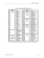
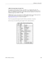
IDE Hard Drive / CD-ROM Interface
One IDE interface is available to connect up to two IDE devices, such as hard disks or CD-ROM
drives. Connector JS4 is the IDE controller with a 44-pin connector. Use CMOS Setup to specify
the drive parameters of the attached drives.
Note:
The two devices connected to this interface are identified as IDE 0 and IDE 1 in
CMOS Setup. The CompactFlash device operates on a different IDE channel and
is identified as IDE 2. IDE 3 is not used in the EPM-32.
Cable length must be 18" or less to maintain proper signal integrity.
This interface supplies power to 2.5" IDE drives. If you are connecting a 3.5" drive to the
interface (using the CBR-4405 44-pin to 40-pin IDE adapter), you must supply external power to
the drive.
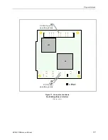
Table 4: JS4 IDE Hard Drive Connector Pinout
Pin
Signal Name
Function
Pin
Signal Name
Function
1
Reset*
Reset signal from CPU
23
DIOW
I/O write
2
Ground
Ground
24
Ground
Ground
3
DD7
Data bus bit 7
25
DIOR
I/O read
4
DD8
Data bus bit 8
26
Ground
Ground
5
DD6
Data bus bit 6
27
IORDY
I/O ready
6
DD9
Data bus bit 9
28
CSEL
Cable select
7
DD5
Data bus bit 5
29
DMACK*
DMA acknowledge
8
DD10
Data bus bit 10
30
Ground
Ground
9
DD4
Data bus bit 4
31
INTRQ
Interrupt request
10
DD11
Data bus bit 11
32
NC
No connection
11
DD3
Data bus bit 3
33
DA1
Device address bit 1
12
DD12
Data bus bit 12
34
CBLID*
Cable type identifier
13
DD2
Data bus bit 2
35
DA0
Device address bit 0
14
DD13
Data bus bit 13
36
DA2
Device address bit 2
15
DD1
Data bus bit 1
37
CS1
Chip select 1
16
DD14
Data bus bit 14
38
CS3
Chip select 3
17
DD0
Data bus bit 0
39
DASP*
LED
18
DD15
Data bus bit 15
40
Ground
Ground
19
Ground
Ground
41
Power
+5.0 V
20
NC
Key
42
Power
+5.0 V
21
PDMARQ
DMA request
43
Ground
Ground
22
Ground
Ground
44
NC
No connection
5
5