


FPGA Registers
EPU-4562 Programmer’s Reference Manual
23
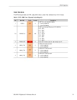
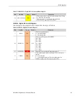
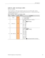
DIOPOLx (x=1,2) – Digital I/O Polarity Control Registers
These two registers control the polarity of the 16 Digital I/O signals.
This reset depends on the state of the FPGA_PSEN signal. If FPGA_PSEN is a ‘0’ then the reset
is the power-on and Platform Reset. If FPGA_PSEN is a ‘1’ then this register is only reset at
power-on.
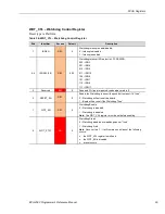
Table 18: DIOPOL1 – Digital I/O 8-1 Polarity Control Register
Bits
Identifier
Access
Default
Description
7-0
POL_DIO[8:1]
R/W
0x00
Sets the DIOx polarity. For each bit:
0 – No polarity inversion
1 – Invert polarity
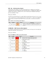
Table 19: DIOPOL2 – Digital I/O 16-9 Polarity Control Register
Bits
Identifier
Access
Default
Description
7-0
POL_DIO[16:9]
R/W
0x00
Sets the DIOx polarity. For each bit:
0 – No polarity inversion
1 – Invert polarity
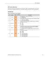
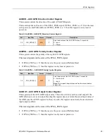
DIOOUTx (x=1,2) – Digital I/O Output Control Registers
These two registers set the DIO output value. This value will only set the actual output if the DIO
direction is set as an output. Reading this register does not return the actual input value of the
DIO (use the DIOIN register for that). As such, this register can actually be used to detect
input/output conflicts.
This reset depends on the state of the FPGA_PSEN signal. If FPGA_PSEN is a ‘0’ then the reset
is the power-on and Platform Reset. If FPGA_PSEN is a ‘1’ then this register is only reset at
power-on.
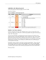
Table 20: DIOOUT1 – Digital I/O 8-1 Output Control Register
Bits
Identifier
Access
Default
Description
7-0
OUT_DIO[8:1]
R/W
0x00
Sets the DIOx output. For each bit:
0 – De-asserts the output (0 if polarity not inverted, 1 if inverted)
1 – Asserts the output (1 if polarity not-inverted, 0 if inverted)
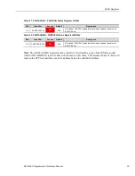
Table 21: DIOOUT2 – Digital I/O 16-9 Output Control Register
Bits
Identifier
Access
Default
Description
7-0
OUT_DIO[16:9]
R/W
0x00
Sets the DIOx output. For each bit:
0 – De-asserts the output (0 if polarity not inverted, 1 if inverted)
1 – Asserts the output (1 if polarity not-inverted, 0 if inverted)
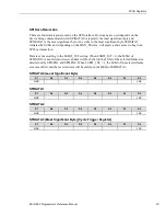
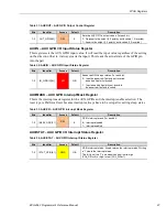
DIOINx (x=1,2) – Digital I/O Input Status Registers
These two registers set the DIO input value. It will read the input value regardless of the setting
on the direction (that is, it always reads the input). This reads the actual state of the DIO pin into
the part.