25
N/7
1
2
1a
2a
L/8
A
F
T
S2
S1
PR
CF
LF
TS
C
G
CIR
CIR
V
V
S
TL1
TL
PA
E
M
P1
P2 P3
P4 P5
P6 P7 P8
1
2 3
4 5
6 7 8
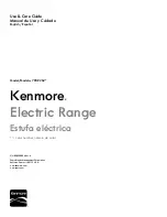
ELECTRIC DIAGRAM KEY
(Schéma électrique)
HOB
(TABLE DE CUISSON)
PA
Ignition switches group
(Groupe d’interrupteurs
d’allumage brûleurs)
A
Ignition coil
(Générateur d’allumage)
OVEN
(FOUR)
F
Oven switch
(Commutateur four)
T
Oven thermostat
(Thermostat four)
S
Bottom element
(Élément chauffant inférieur)
C
Top element
(Élément chauffant supérieur)
G
Broil element
(Élément chauffant de gril)
CIR
Circular element
(Élément chauffant circulaire)
S1
Oven temperature indicator light
(Voyant de la
température du four)
S2
Oven power on indicator light
(Voyant de
fonctionnement du four)
V
Oven fan
(Ventilateur du four)
LF
Oven lamps
(Lampes du four)
PR
Electronic programmer
(Programmateur
électronique)
OTHERS
(AUTRES)
CF
Cooling fan
(Ventilateur de réfroidissement)
TL1
Cooling fan thermal limiter
(Limiteur de température
ventilateur de réfroidissement)
TS
Safety thermal overload
(Thermolimitateur de sécurité)
M
Terminal block
(Bornier)
E
Earth connection
(Connection de terre
)
3
WIRING DIAGRAM